Energy-recovery hydraulic system and engineering machinery

A hydraulic system and energy recovery technology, which is applied to fluid pressure actuation system components, mechanical equipment, fluid pressure actuation devices, etc., can solve the problems of reduced recovery rate, increased loss of energy recovery hydraulic circuit, low energy recovery utilization rate, etc. Problems, low cost, large oil pressure range, easy to achieve

Active Publication Date: 2014-12-31
昆山三一动力有限公司
View PDF8 Cites 0 Cited by
  • Summary
  • Abstract
  • Description
  • Claims
  • Application Information

AI Technical Summary

Problems solved by technology

[0004] The energy recovery hydraulic system in the related art has at least the following disadvantages: the hydraulic hybrid power system uses an accumulator, the capacity of the accumulator matches the single slewing deceleration braking energy under the standard cycle, and the effect of this system is relatively low under the standard cycle. Good, but when there are non-standard working conditions such as low or large slewing deceleration and braking energy, the energy recovery utilization rate is low; when the pressure of the accumulator is close to the maximum working pressure, the loss of the energy recovery hydraulic circuit increases, and the recovery rate reduce

Method used


Image

  • Energy-recovery hydraulic system and engineering machinery

Examples


Embodiment Construction

[0029] In order to understand the above-mentioned purpose, features and advantages of the present invention more clearly, the present invention will be further described in detail below in conjunction with the accompanying drawings and specific embodiments.

[0030] In the following description, many specific details are set forth in order to fully understand the present invention, but the present invention can also be implemented in other ways different from those described here, therefore, the present invention is not limited to the specific embodiments disclosed below limit.

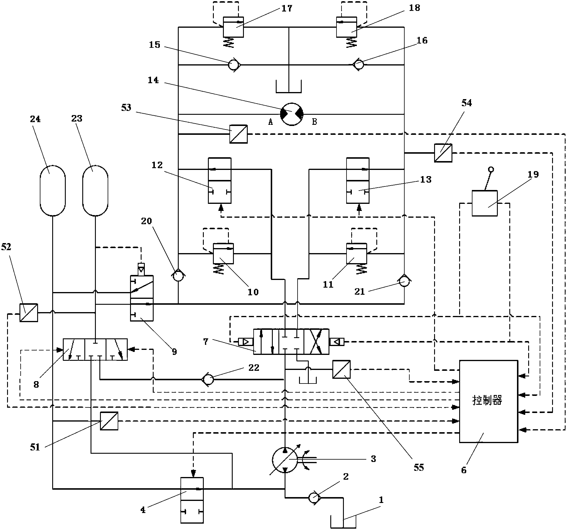
[0031] Such as figure 1 As shown, the energy recovery hydraulic system according to the embodiment of the present invention includes a hydraulic motor 14, a first solenoid valve 12, a second solenoid valve 13, a first reversing valve 7, a hydraulic control valve 9, a plurality of accumulators, Hydraulic pump 3, first one-way valve 15, second one-way valve 16 and controller 6, wherein, the outlet of hyd...


PUM


Abstract

The invention provides an energy-recovery hydraulic system, comprising a hydraulic motor, a first electromagnetic valve, a second electromagnetic valve, a first reversing valve, a hydraulic control valve, a plurality of energy accumulators, a hydraulic pump, a first one-way valve, a second one-way valve and a controller, wherein a first oil port and a second oil port of the hydraulic motor are respectively connected to the plurality of energy accumulators through the hydraulic control valve, and during braking, pressure oil supplied by the hydraulic motor is injected into the plurality of energy accumulators through the hydraulic valve. According to the energy-recovery hydraulic system, the plurality of energy accumulators are adopted for gradual energy storage, so that high energy recovery rate and wide recovery range are achieved; when recovered energy is low, the energy can also be utilized fully; in an energy release process, when the pressure in each energy accumulator is lower than a certain value, residual oil is taken as incoming oil of the hydraulic pump, so that the problem that the energy is more difficult to utilize when the pressure of the energy accumulators is lower is solved; and the energy-recovery hydraulic system is simple and convenient to implement and low in cost. The invention further provides engineering machinery consisting of the energy-recovery hydraulic system.

Description

technical field [0001] The invention relates to the field of hydraulic technology, in particular to an energy recovery hydraulic system and construction machinery including the energy recovery hydraulic system. Background technique [0002] Slewing is a very frequent action in the working process of hydraulic excavators, and the frequent starting and braking of the slewing mechanism will cause impact on the hydraulic system. Due to the large mass of the upper mechanism of the slewing mechanism of the excavator, the slewing inertia is also large, and a large amount of heat will be generated during braking. According to statistics, the energy consumption of the rotary mechanism of hydraulic excavators accounts for about 25% to 40% of the energy consumption in the working process of the excavator, and the heat generated by the rotary hydraulic oil circuit accounts for about 30% to 40% of the total heat generated by the hydraulic system. Therefore, if the slewing braking energy...

Claims


Application Information

Patent Timeline
Patent Type & Authority Patents(China)
IPC IPC(8): F15B21/14F15B1/02
Inventor 孙普邓敏华阎智慧
Owner 昆山三一动力有限公司
Why Eureka
Try Eureka