
Underwater video shooting system

A technology of underwater photography and camera, applied in the field of robotics, to achieve the effect of three-dimensional realization

Inactive Publication Date: 2017-11-07
SHANGHAI UNIV
View PDF9 Cites 9 Cited by
  • Summary
  • Abstract
  • Description
  • Claims
  • Application Information

AI Technical Summary

Problems solved by technology

[0005] The purpose of the present invention is to solve the problems existing in the prior art, and to provide an underwater camera system for stable and three-dimensional shooting with multiple backgrounds in a complex underwater environment, so as to meet the needs of underwater multi-functional camera

Method used


Image

  • Underwater video shooting system
  • Underwater video shooting system

Examples


Embodiment 1

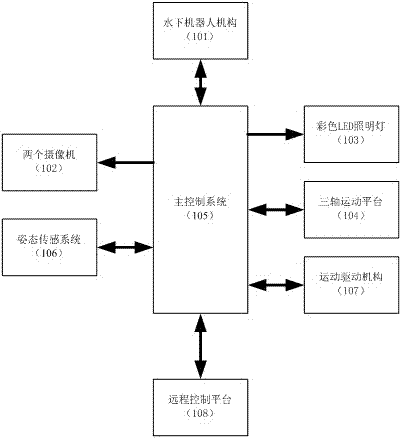
[0021] Such as figure 1 As shown, the underwater camera system includes: an underwater robot mechanism (101), two cameras (102), a colored LED lighting lamp (103), a three-axis motion platform (104), a main control system ( 105), an attitude sensing system (106), a motion drive mechanism (107) and a remote control platform (108), characterized in that two cameras (102), Colored LED lighting (103), three-axis motion platform (104), main control system (105), attitude sensing system (106) and motion drive mechanism (107), the main control system (105) communicates with the remote The control platform (108) is connected to realize real-time remote control and image data transmission control, and the main control system (105) is connected with the two cameras (102), the color LED lighting (103), and the three-axis motion platform respectively. (104), the attitude sensing system (106) is connected with the motion driving mechanism (107), and is used to realize the motion control o...

Embodiment 2

[0023] This embodiment is basically the same as Embodiment 1, especially in that:

[0024] The two cameras (102) are combined to form an underwater binocular camera system, which can realize the stereo camera function and photographing function of underwater images, and obtain the depth information of the captured images.

[0025] The color LED lighting lamp (103) adopts four high-power controllable LEDs of white, red, green and blue to form a color variable lighting LED array, which is used to realize the changeable and adjustable color lighting of the underwater environment background.

[0026] The three-axis motion platform (104) is used to fix the two cameras (102), and is used to realize attitude control of the cameras (102), so as to complete target tracking and anti-disturbance stability control.

[0027] The attitude sensing system (106) uses a nine-axis degree of freedom sensor GY-85, which includes a three-axis accelerometer ADXL345, a three-axis gyroscope ITG3205 an...

Embodiment 3

[0032] This embodiment is basically the same as Embodiment 1, especially in that:

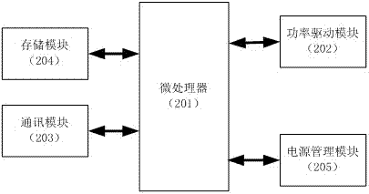
[0033] see figure 2, the main control system (105) in this underwater camera system includes a microprocessor (201), a power drive module (202), a communication module (203), a storage module (204) and a power management module (205), so The microprocessor (201) is respectively connected to the motion drive mechanism (107), the colored LED lighting (103) and the three-axis motion platform (104) via the power drive module (202) to realize the Motion control of the underwater robot mechanism (101), underwater environment lighting and attitude control of the camera (102), the microprocessor (201) communicates with the remote The control platform (108) realizes remote communication control and real-time data transmission, the microprocessor (201) is connected to the attitude sensing system (106) by using the IIC bus to obtain attitude information, and the microprocessor (201) and the The camera ...


PUM


Abstract

The invention discloses an underwater video shooting system. The underwater video shooting system comprises an underwater robot mechanism, two video cameras, a colorful LED illumination lamp, a triaxial motion platform, a main control system, an attitude sensing system, a motion driving mechanism, and a remote control platform. The two video cameras, the colorful LED illumination lamp, the triaxial motion platform, the main control system, the attitude sensing system, and the motion driving mechanism are disposed in the underwater robot mechanism. The main control system is connected with the remote control platform by an optical fiber, and is used for realizing real-time remote control and image data transmission control. The main control system is connected with the two video cameras, the colorful LED illumination lamp, the triaxial motion platform, the attitude sensing system 106, and the motion driving mechanism, and then the motion control of the underwater robot mechanism in the water and underwater environment illumination control are realized, and according to attitude information acquired by the attitude sensing system, the triaxial motion platform is regulated in a real-time manner, and then the attitude stability and the target tracking of the video cameras are maintained, and then a binocular three-dimensional video shooting and photo shooting function in the underwater environment is realized in a real-time manner. The underwater video shooting system is widely used for the video shooting application in the underwater environment.

Description

technical field [0001] The invention relates to the field of robots, in particular to an underwater camera system applied to underwater environment photography. Background technique [0002] In the process of underwater environment photography, the camera carrier underwater robot will inevitably be disturbed by the environmental water flow, which will lead to the failure of camera target tracking and camera drift in the process of underwater photography. At the same time, in order to better realize the underwater environment For photography, it is necessary to adjust the light sources of different background colors and obtain the depth information of underwater images to achieve the effect of underwater stereoscopic photography. [0003] Chinese Utility Model Patent Specification Publication (Announcement) No.: CN203872256U discloses an "underwater camera system", which can realize underwater environment photography, but this underwater camera system cannot realize underwate...

Claims


Application Information

Patent Timeline
Patent Type & Authority Applications(China)
IPC IPC(8): G05B19/042G05D1/00G05D1/10G05D3/12G05D25/02H04N5/225H04N5/232H04N5/235H04N5/247H04N13/02H04N23/90
CPCG05D1/0094G05D1/10H04N13/204G05B19/042G05D3/12G05D25/02G05B2219/2651G05B2219/25252H04N23/56H04N23/66H04N23/74H04N23/90
Inventor 唐智杰
Owner SHANGHAI UNIV
Learn More