A kind of reinforcement method of ccga device

A device and PCB board technology, applied in the field of CCGA device reinforcement, can solve the problems of inability to meet product application environment requirements, solder joint cracking, low cost, etc., and achieve the effect of solving the problem of solder joint cracking failure, reliable electrical connection, and easy operation.

Active Publication Date: 2019-05-07
XIAN MICROELECTRONICS TECH INST
View PDF4 Cites 0 Cited by
  • Summary
  • Abstract
  • Description
  • Claims
  • Application Information

AI Technical Summary

Problems solved by technology

Tin-lead columns are lower in cost than wound columns, but their strength is low. Commonly used reinforcement processes are prone to cracking of solder joints, which cannot meet the application environment requirements of the product.

Method used

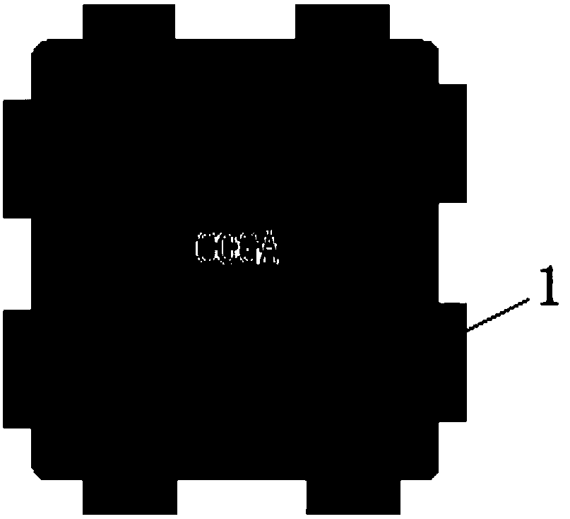
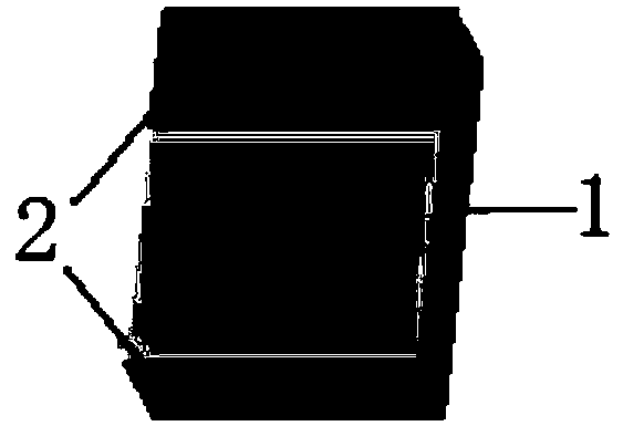
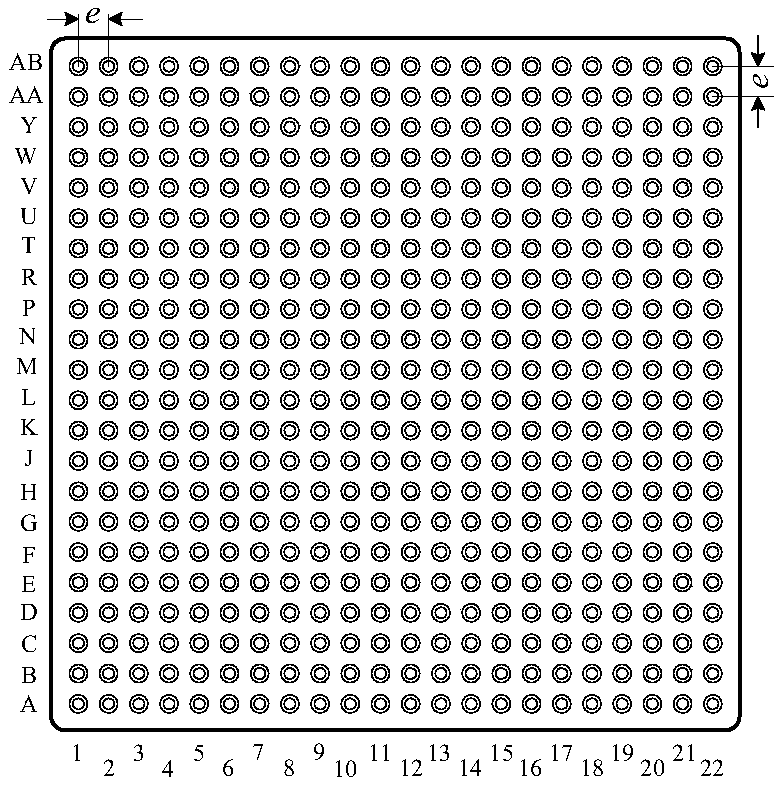

Image

  • A kind of reinforcement method of ccga device
  • A kind of reinforcement method of ccga device
  • A kind of reinforcement method of ccga device

Examples


Embodiment

[0037] The verification conditions are formulated according to ECSS-Q-ST-70-08C The manual soldering of high-reliability electrical connections ECSS-Q-ST-70-38C and high-reliability soldering for surface-mount and mixed technology.

[0038] Table 1 LCDSP0102 device CCGA484 package size table

[0039]

[0040] see image 3 , make test printed circuit board, CCGA device is installed on the printed circuit board and strengthened by the method of the present invention, made a group of samples reinforced with epoxy glue and carried out comparative test simultaneously, test according to such as Figure 4 The test procedure shown and the test conditions shown in Table 2 were carried out.

[0041] Table 2 Test verification conditions

[0042]

[0043]

[0044]


PUM


Abstract

The invention discloses a CCGA device reinforcing method. An epoxy glass cloth layer laminate is used to produce a reinforcing adhesive sheet having a cuboid-shaped structure, and after assembly of a CCGA device, the epoxy adhesive is used to glue the reinforcing adhesive sheet on the periphery of the CCGA device, and then is solidified to complete the reinforcing. A spot weld cracking failure problem caused by temperature and mechanical stress is solved, and a verification condition requirement is satisfied.

Description

technical field [0001] The invention belongs to the field of electronic systems and equipment, and in particular relates to a CCGA device strengthening method. Background technique [0002] Compared with CBGA devices, CCGA devices have better stress release ability after assembly on printed circuit boards, so CCGA devices are generally used instead of CBGA devices in high-reliability electronic products. There are two types of welding pillars for CCGA devices, one is tin-lead pillars, and the other is wound pillars. Tin-lead columns are lower in cost than wound columns, but their strength is low. Commonly used reinforcement techniques are prone to cracking of solder joints, which cannot meet the application environment requirements of the product. Contents of the invention [0003] The technical problem to be solved by the present invention is to provide a CCGA device reinforcement method for the deficiencies in the above-mentioned prior art, solve the solder joint cracki...

Claims


Application Information

Patent Timeline
Patent Type & Authority Patents(China)
IPC IPC(8): H01L21/56H01L23/00
Inventor 陈元章徐麒凯杜磊
Owner XIAN MICROELECTRONICS TECH INST
Why Eureka
Try Eureka