Electronic cam needle insertion system

An electronic cam and pin technology, which is applied in the field of pins and connectors, can solve problems such as not being able to meet production needs, and achieve the effects of facilitating automatic control, improving efficiency, and saving production costs

Pending Publication Date: 2017-11-07
KUNSHAN LEAGUE AUTOMECHANISM
View PDF0 Cites 6 Cited by
  • Summary
  • Abstract
  • Description
  • Claims
  • Application Information

AI Technical Summary

Problems solved by technology

[0003] The existing cam pin structure and method cannot meet the existing production needs. Therefore, it is necessary to develop a cam structure that can meet the pins of various types of connectors.

Method used


Image

  • Electronic cam needle insertion system

Examples


Embodiment Construction

[0031] The following description of the embodiments refers to the accompanying drawings to illustrate specific embodiments in which the invention may be practiced. The directional terms mentioned in the present invention, such as "up", "down", "front", "back", "left", "right", "top", "bottom", etc., are only for reference to the attached drawings. direction. Therefore, the directional terms used are used to illustrate and understand the present invention, but not to limit the present invention.

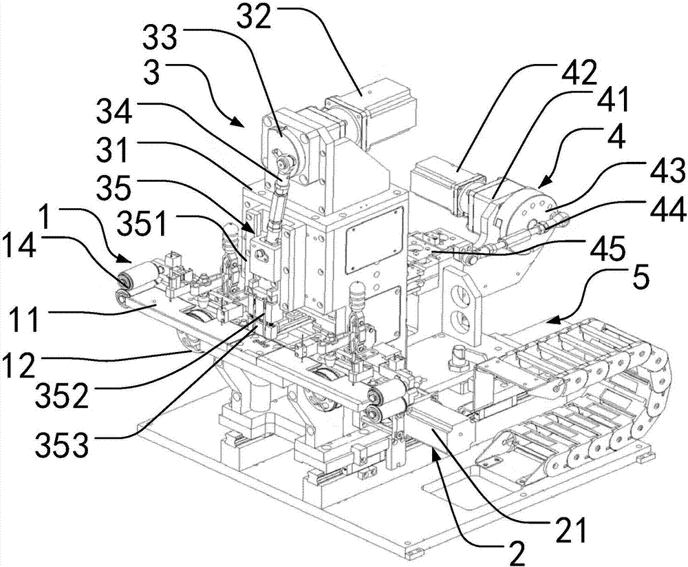
[0032] Examples such as figure 1 As shown, an electronic cam needle insertion system includes a needle feeding mechanism 1, a needle taking mechanism 2, a needle cutting mechanism 3, a needle insertion mechanism 4, and a control system.

[0033] In this embodiment, the X-axis direction is defined as the horizontal direction, the vertical direction perpendicular to the X-axis is defined as the Z-axis direction, and the horizontal direction perpendicular to the X-axis is defined as th...


PUM


Abstract

The invention discloses an electronic cam needle insertion system, comprising a needle feeding mechanism arranged along the X-axis direction, defining the X-axis direction as a horizontal direction, the needle sending mechanism is used to transport the insertion needles; the needle taking mechanism is assembled on the The needle sending mechanism is used to obtain the insertion needles on the needle sending mechanism; the needle cutting mechanism is assembled above the needle sending mechanism, and the needle cutting mechanism is used to cut the insertion needles on the needle taking mechanism into shape The pin insertion mechanism is assembled with the needle cutting mechanism, and the pin insertion mechanism is used to insert the sheared and formed pins on the connector; the pin depth adjustment mechanism is assembled with the pin insertion mechanism, The needle insertion depth adjustment mechanism is used to adjust the needle insertion depth; the control system is used to integrally control the needle feeding mechanism, needle removal mechanism, needle cutting mechanism, needle insertion mechanism, and needle insertion depth adjustment mechanism to simulate the cam to insert The pins are plugged into the connector.

Description

technical field [0001] The invention relates to the fields of connectors, pins and the like, in particular to an electronic cam pin system. Background technique [0002] When assembling the connector, it is usually necessary to insert and assemble the pins into the connector. The existing pin insertion method is realized by a cam pin insertion machine. With this purely mechanical cam structure, the curvature of motion of each cam pin insertion is fixed. Therefore, each cam pin insertion machine is usually only for one class product, that is, each cam can only complete the pins of the corresponding type of connector. However, in actual production, there are many types of connectors, therefore, different types of cams are required to complete the production. [0003] The existing cam pin structure and method cannot meet the existing production requirements. Therefore, it is necessary to develop a cam structure that can meet the pins of various types of connectors. Contents...

Claims


Application Information

Patent Timeline
Patent Type & Authority Applications(China)
IPC IPC(8): H01R43/20
CPCH01R43/20
Inventor 肖辉吴海东
Owner KUNSHAN LEAGUE AUTOMECHANISM
Why Eureka
Try Eureka