Stroke limit adjustment device for push rod
A stroke limit and adjustment device technology, applied in electromechanical devices, control mechanical energy, electrical components, etc., can solve the problems of limiting the universality of push rods, unsatisfactory performance, time-consuming and labor-intensive, etc., to achieve simple structure, easy operation, control Simple way to effect
- Summary
- Abstract
- Description
- Claims
- Application Information
AI Technical Summary
Problems solved by technology
Method used
Image
Examples
specific Embodiment 1
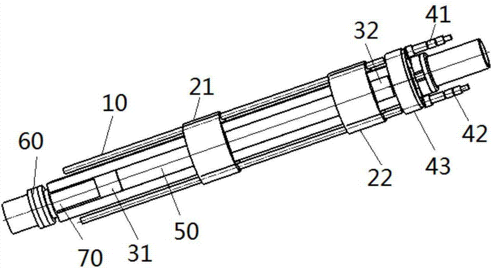
[0030] Such as figure 1As shown, this specific embodiment discloses a travel limit adjustment device for a push rod, including a guide rail 10 for guiding the push rod 50 and a first switch seat 21 and a second switch seat 21 movably arranged on the guide rail 10 The distance between the switch base 22 , the first switch base 21 and the second switch base 22 along the moving direction of the push rod 50 is adjustable. A first switch (not shown in the figure) is fixedly arranged on the first switch seat 21 , and a second switch (not shown in the figure) is fixedly arranged on the second switch seat 22 . The push rod 50 is provided with a first trigger 31 for triggering the first switch and a trigger for triggering the second switch. Driven by the push rod 50, the first trigger 31 and the second trigger 32 trigger the first switch respectively. and the second switch. Wherein, the first switch has a first trigger handle, the second switch has a second trigger handle, and both t...
specific Embodiment 2
[0039] This specific embodiment discloses another stroke limit adjusting device of a push rod, the structure of which is basically the same as that of the specific embodiment 1, except that the trigger information sent by the two triggers in the two embodiments is different. In the first specific embodiment, the two triggers send and receive trigger information by contacting the trigger handles of the two switches respectively. In this specific embodiment, the trigger does not need to be in direct contact with the switch. information to send and receive trigger information.
[0040] In this specific embodiment, the first switch has a first sensor, the second switch has a second sensor, the first trigger is provided with first identification information, and the second trigger is provided with second identification information. When the first trigger moves to the first switch, the first sensor recognizes the first identification information and turns on the first switch, turns ...
specific Embodiment 3
[0042] This specific embodiment discloses another stroke limit adjustment device for a push rod, its structure is basically the same as that of the specific embodiment 1, the difference is that the specific embodiment 1 uses two triggers to trigger two switches respectively, and the In this embodiment, a trigger is used to move between the two switches, thereby triggering the two switches respectively.
[0043] In this specific embodiment, the stroke limit adjusting device of the push rod includes a trigger fixedly arranged on the push rod, and the trigger moves between the first switch and the second switch driven by the push rod. Specifically, the first switch has a first trigger handle, the second switch has a second trigger handle, and both the first trigger handle and the second trigger handle extend into the guide rail.
[0044] When the trigger moves to the first switch, the trigger contacts the first trigger handle, the trigger sends the third trigger information, the ...
PUM
 Abstract
Description
Claims
Application Information
 - R&D
- Intellectual Property
- Life Sciences
- Materials
- Tech Scout
- Unparalleled Data Quality
- Higher Quality Content
- 60% Fewer Hallucinations
Browse by: Latest US Patents, China's latest patents, Technical Efficacy Thesaurus, Application Domain, Technology Topic, Popular Technical Reports.
© 2025 PatSnap. All rights reserved.Legal|Privacy policy|Modern Slavery Act Transparency Statement|Sitemap|About US| Contact US: help@patsnap.com

