Hydrolytic acidification reactor for sewage plant in industrial zone

A technology of hydrolysis and acidification, industrial park, applied in chemical instruments and methods, biological water/sewage treatment, water/sludge/sewage treatment, etc., can solve the problems of poor water quality and quantity fluctuation, poor biodegradability of wastewater, etc., to achieve uniform water quality The effect of reducing water volume, reducing infrastructure costs and reducing biogas production

Inactive Publication Date: 2017-11-10
HARBIN INST OF TECH
View PDF5 Cites 3 Cited by
  • Summary
  • Abstract
  • Description
  • Claims
  • Application Information

AI Technical Summary

Problems solved by technology

[0005] The purpose of the present invention is to solve the problems of poor biodegradability and poor fluctuation of water quality and quantity of wastewater in existing industrial parks, and provide a hydrolysis acidification reactor for sewage plants in industrial parks

Method used


Image

  • Hydrolytic acidification reactor for sewage plant in industrial zone
  • Hydrolytic acidification reactor for sewage plant in industrial zone

Examples


specific Embodiment approach 1

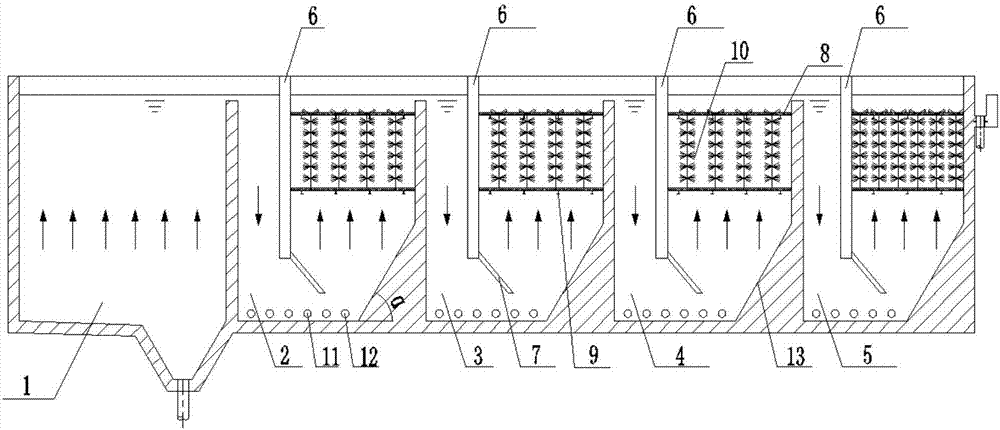
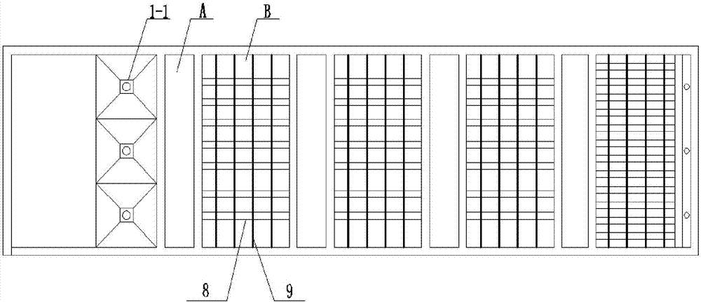
[0015] Specific Embodiment 1: The hydrolytic acidification reactor of the industrial park sewage plant in this embodiment includes a reactor, 5 cells, 4 baffles 6, elastic packing 10, threaded steel 8, support 9, sludge discharge pipe 11 and The aeration pipe 12 is divided into 5 compartments in the reactor by a partition wall, and along the flow direction of the sewage are the first compartment 1, the second compartment 2, the third compartment 3, and the fourth compartment 4 And the fifth compartment 5, a sludge hopper 1-1 is arranged at the bottom of the first compartment 1, vertically in the second compartment 2, the third compartment 3, the fourth compartment 4 and the fifth compartment 5 A baffle plate 6 is arranged directly, and a deflector 7 is arranged on the lower part of the baffle plate 6, and the second compartment 2 is divided into a downflow area A and an upflow area B by the baffle plate 6, and the baffle plate A water flow channel is formed between the plate 6...

specific Embodiment approach 2

[0017] Embodiment 2: This embodiment differs from Embodiment 1 in that the sludge hopper 1-1 is connected to the sludge discharge pipe.

specific Embodiment approach 3

[0018] Embodiment 3: The difference between this embodiment and Embodiment 1 or 2 is that the angle between the baffle plate 6 and the deflector 7 is 140°, and the deflector 7 is inclined toward the upwelling area B.

[0019] In this embodiment, the water flow channel is narrowed by the deflector, the water flow is accelerated, and the mixing is uniform.


PUM

PropertyMeasurementUnit
angleaaaaaaaaaa

Abstract

The invention discloses a hydrolytic acidification reactor for a sewage plant in an industrial zone, relates to a hydrolytic acidification reactor, and aims to solve the problems of poor wastewater biodegradability and poor water quality and volume fluctuation of an existing industrial zone. The hydrolytic acidification reactor is divided into five compartments by partition walls, wherein a sludge pit is arranged at the bottom of the first compartment; a deflection baffle is vertically arranged in each of the second compartment, the third compartment, the fourth compartment and the fifth compartment; the second compartment is divided into a downwelling region and an upwelling region by the deflection baffle; an elastic filler is arranged in the upwelling region of the second compartment in a hanging manner; a dredge pipe and an aerator pipe are arranged at the bottom of the second compartment; the structures of the third compartment, the fourth compartment and the fifth compartment are the same as that of the second compartment; the density of an elastic filler in the fifth compartment is higher than the density of the elastic filler in the second compartment. According to the hydrolytic acidification reactor, the hydraulic flow state is optimized by deflection baffle structures, loss of sludge is reduced by the high-density filler in the last compartment, and a hydrolytic acidification effect is improved.

Description

technical field [0001] The invention relates to a hydrolysis acidification reactor. Background technique [0002] In our country, as the new focus of regional economic development, industrial parks have sprung up like mushrooms, and many industrial parks have achieved economic benefits, and even become regional image projects. As of the end of 2010, there were 83 state-level high-tech zones and 107 state-level economic and technological development zones in my country; the number of national eco-industrial demonstration parks under construction through planning and demonstration reached 39, of which 12 national eco-industrial demonstration parks passed the inspection and acceptance indivual. All provinces, most cities and even some counties in China have started to build their own industrial parks. Industry researchers pointed out that at present, regional governments regard the construction of industrial parks as a new engine to stimulate regional economic growth, and have...

Claims


Application Information

Patent Timeline
Patent Type & Authority Applications(China)
IPC IPC(8): C02F3/30
CPCC02F3/301C02F2203/004C02F2203/006C02F2301/028
Inventor 祁佩时赵可周超陈瑜
Owner HARBIN INST OF TECH
Why Eureka
Try Eureka