Combustion chamber of a pulse detonation engine

A technology of pulse detonation and combustion chamber, which is applied in the direction of machines/engines, rocket engine devices, mechanical equipment, etc. It can solve the problems of large influence of flow resistance and ablation, and achieve the reduction of frontal flow resistance, increase of thrust, and not easy to burn Eclipse effect

Inactive Publication Date: 2019-03-26
NORTHWESTERN POLYTECHNICAL UNIV
View PDF7 Cites 0 Cited by
  • Summary
  • Abstract
  • Description
  • Claims
  • Application Information

AI Technical Summary

Problems solved by technology

[0004] Invention patent 201310059114.9 discloses "a pulse detonation engine combustion chamber structure". Although the pulse detonation engine combustion chamber structure reduces the flow resistance, the impact of the flow resistance is still great, and the problem of ablation also appears

Method used


Image

  • Combustion chamber of a pulse detonation engine
  • Combustion chamber of a pulse detonation engine
  • Combustion chamber of a pulse detonation engine

Examples


Embodiment Construction

[0020] This embodiment is a pulse detonation engine combustion chamber.

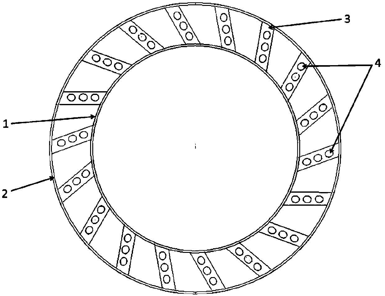
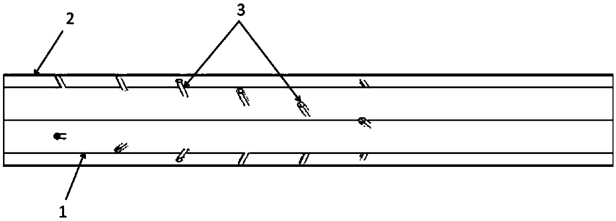
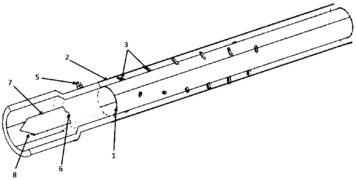
[0021] refer to figure 1 , figure 2 , the combustion chamber of the pulse detonation engine in this embodiment includes a combustion chamber wall surface 1, an air inlet casing 2, a drainage section 3, and an air intake hole 4, wherein, the air inlet casing 2 and the combustion chamber wall surface 1 are provided with Multi-row air intake devices, each exhaust dynamic air intake device is separated by 0.5 to 1 times the diameter of the combustion chamber. The air intake device is composed of a drainage section 3 and an air intake hole 4, and the air channel casing 2 forms a circular secondary air intake channel. The drainage section 3 is a hollow cylinder connecting the inlet casing 2 and the wall of the engine. The cylinder has the same inclination along the axial and circumferential directions of the engine, and a plurality of air inlets are arranged on the front wall of the cylinder. Multiple rows...


PUM


Abstract

The invention discloses a pulse-detonation engine combustion chamber, and belongs to the technical field of detonation engines. A plurality of rows of gas inlet devices are arranged on a gas inlet path housing and the combustion chamber wall surface; and every two rows of pneumatic gas inlet devices are spaced by a distance which is 0.5-1 time the diameter of the combustion chamber. Each gas inlet device is composed of a drainage section and a gas inlet, wherein the gas inlet path housing defines a circular ring shaped secondary gas inlet path, the drainage section is in the form of a hollow cylinder connecting the gas inlet path housing to the engine wall surface, the cylinder has the same angles of inclination in the axial direction and the peripheral direction of an engine, and a plurality of gas inlets are formed in the front wall surface of the cylinder. The plurality of rows of gas inlet devices are uniformly distributed in a staggered mode in the peripheral direction of the combustion chamber, and positions of the rear row of gas inlet devices are determined by rotating positions of the front row of gas inlet devices clockwise. Other parts are not arranged inside the combustion chamber, so that the service life of the combustion chamber is long; and the drainage sections are arranged outside the combustion chamber, so that internal flow resistance of the detonation chamber is effectively reduced.

Description

technical field [0001] The invention relates to the technical field of detonation engines, in particular to a pulse detonation combustion chamber based on aerodynamic turbulence enhanced detonation. Background technique [0002] The pulse detonation engine is a new concept propulsion device that uses high-temperature, high-pressure gas generated by intermittent detonation waves to generate thrust. Pulse detonation engines can be divided into rocket-type pulse detonation engines and air-breathing pulse detonation engines according to whether they have their own oxidant. [0003] There are two ways of detonation detonation, one is direct detonation and the other is indirect detonation. Direct detonation requires a huge amount of ignition energy, which is not practical; indirect detonation is to form a detonation wave through the transition from slow combustion to detonation, using a small ignition energy to form a slow combustion wave, and then through a series of DDT enhance...

Claims


Application Information

Patent Timeline
Patent Type & Authority Patents(China)
IPC IPC(8): F02K7/02F02K9/62
CPCF02K7/02F02K9/62
Inventor 黄希桥冯翔洲王苗苗李前翔郑龙席
Owner NORTHWESTERN POLYTECHNICAL UNIV
Why Eureka
Try Eureka