
Soft film pressure sensor

A film pressure and sensor technology, applied in the field of soft film pressure sensor, can solve the problems of test repeatability difference, hysteresis effect, etc., achieve the effect of light, thin and small size, change hysteresis effect, and improve sensitivity

Pending Publication Date: 2017-11-10
SUZHOU LEANSTAR ELECTRONICS TECH
View PDF7 Cites 7 Cited by
  • Summary
  • Abstract
  • Description
  • Claims
  • Application Information

AI Technical Summary

Problems solved by technology

[0005] The purpose of the present invention is to provide a soft film pressure sensor that can further improve the sensitivity of the sensor through the synergistic effect of the resistivity change of the new nano pressure sensitive material and the change of the contact area of ​​the two pressure sensitive layers, and then supplemented with a suitable Young's modulus The ultra-thin film substrate solves the problems of hysteresis effect and test repeatability difference

Method used

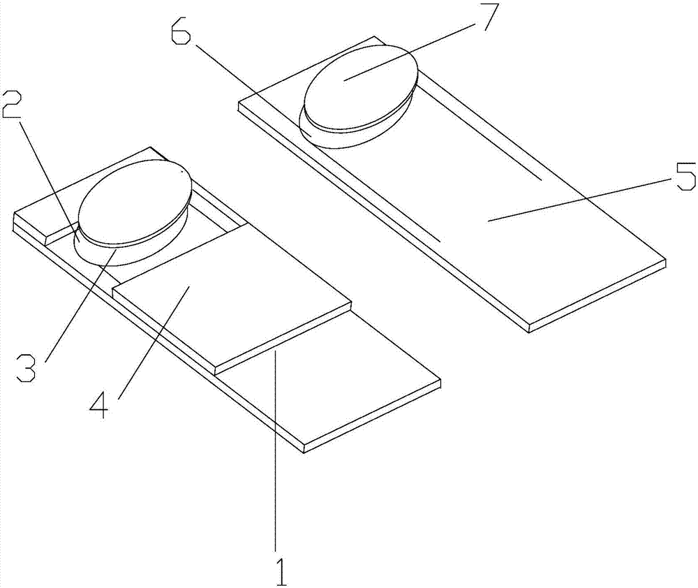
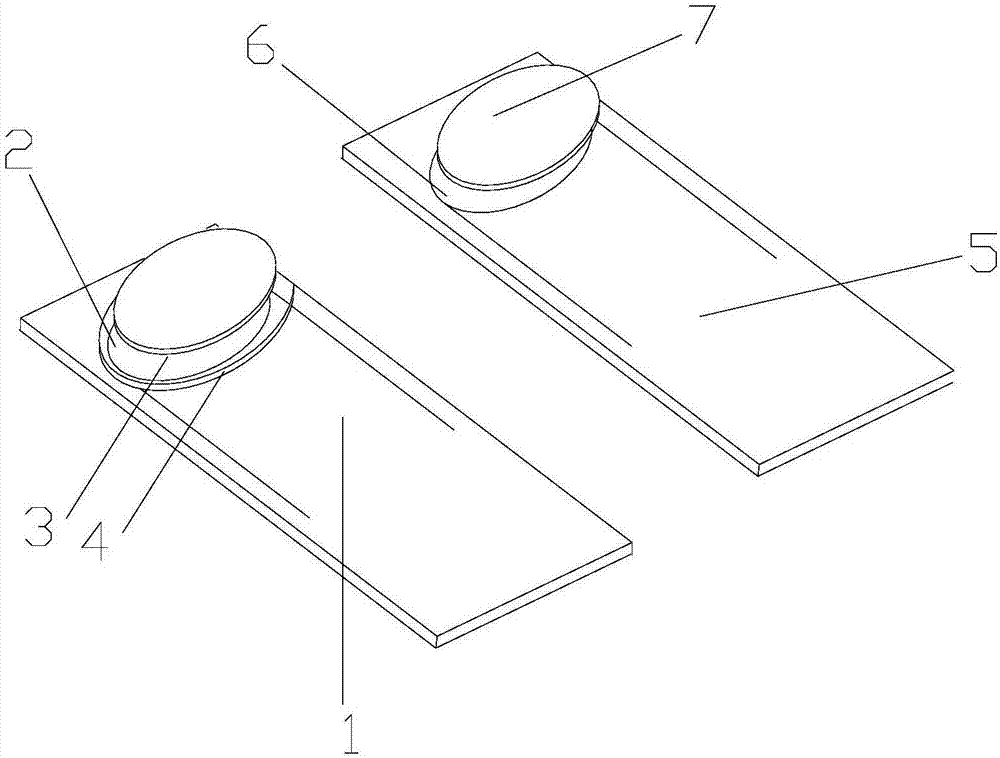
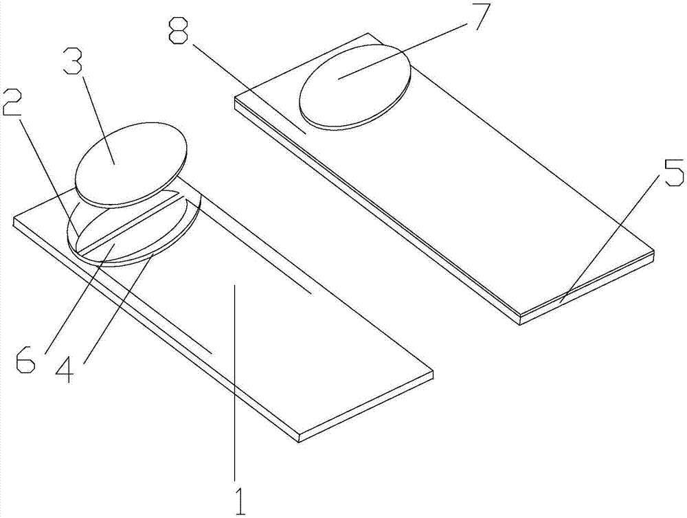

Image

  • Soft film pressure sensor
  • Soft film pressure sensor
  • Soft film pressure sensor

Examples


Embodiment approach 2

[0035] Implementation mode two: if figure 2As shown, it includes a first flexible substrate, a first electrode layer, a first pressure-sensitive layer, a supporting layer, a second flexible substrate, and a second electrode layer. The first electrode layer is located on the surface of the first flexible substrate and is in close contact with the substrate, the first pressure-sensitive layer covers the surface of the first electrode layer and is in close contact with the electrode layer; the support layer is located on the surface of the first pressure-sensitive layer or the support layer Located on the surface of the flexible substrate and surrounding the first pressure-sensitive layer or the supporting layer is located on the surface of the flexible substrate and on the side of the first pressure-sensitive layer; the second electrode layer is located on the surface of the second flexible substrate and connected to the substrate Close contact.

Embodiment approach 3

[0036] Implementation mode three: if image 3 As shown, it mainly includes a first flexible substrate, a first electrode layer, a second flexible substrate, a second conductive layer, a second pressure-sensitive layer, and a supporting layer. The first electrode layer is located on the surface of the first flexible substrate and is in close contact with the substrate, the second conductive layer is located on the surface of the second flexible substrate and is in close contact with the substrate, and the second pressure-sensitive layer covers the surface of the second conductive layer and in close contact with the conductive layer; the supporting layer is located on the surface of the second pressure-sensitive layer or the supporting layer is located on the surface of the second flexible substrate and surrounds the second pressure-sensitive layer or the supporting layer is located on the surface of the second flexible substrate and on the second flexible substrate Two sides of...


PUM

PropertyMeasurementUnit
thicknessaaaaaaaaaa
widthaaaaaaaaaa

Abstract

The invention relates to a design of a pressure sensor, and particularly relates to a soft film pressure sensor, wherein the sensitivity of the sensor is further improved based on the synergistic effect of changing the resistivity of novel nanometer pressure-sensitive materials and changing the contact area of two pressure-sensitive layers, and the problems of hysteresis effect and poor test repeatability are solved with the assistance of an ultra-thin film substrate having a proper young modulus. The soft film pressure sensor comprises a first flexible substrate, a first electrode layer, a first pressure-sensitive layer, a supporting layer, a second flexible substrate, a second electrode layer and a second pressure-sensitive layer. The first pressure-sensitive layer, the first electrode layer and the first flexible substrate are sequentially connected. The second pressure-sensitive layer, the second electrode layer and the second flexible substrate are sequentially connected. The soft film pressure sensor further comprises the supporting layer positioned between the first soft substrate and the second the flexible substrate and used for fixing the first pressure-sensitive layer and the second pressure-sensitive layer. A gap is formed between the first pressure-sensitive layer and the second pressure-sensitive layer.

Description

technical field [0001] The invention relates to the design of a pressure sensor, in particular to a soft film pressure sensor. Background technique [0002] In recent years, due to the advantages of good stability, small size and high reliability, thin-film pressure sensors have been widely used in industry. Thin film pressure sensor is generally considered as an ultra-thin multi-layer electromechanical device, in which electrodes and connecting wires are arranged in an orderly manner on the sensing element and its lamination structure, and a solid structure is made of suitable polymer film and epoxy resin materials. ultra-thin package structure. When the membrane pressure sensor is subjected to a sudden contact pressure or a continuously changing pressure, tension, or velocity field, an electrical signal will be generated for outputting corresponding indications and / or actuating the control and operation of the machine. [0003] In general, thin-film pressure sensors incl...

Claims


Application Information

Patent Timeline
Patent Type & Authority Applications(China)
IPC IPC(8): G01L1/16
CPCG01L1/16
Inventor 熊作平张珽谷文井华王冉
Owner SUZHOU LEANSTAR ELECTRONICS TECH
Learn More