Optical interface and light transmit-receive assembly

An optical transceiver component and optical interface technology, applied in the field of communications, can solve the problems of complex adapter manufacturing process, increased cost, and complicated optical interface manufacturing work.

Active Publication Date: 2017-11-10
HUAWEI MACHINERY
View PDF5 Cites 3 Cited by
  • Summary
  • Abstract
  • Description
  • Claims
  • Application Information

AI Technical Summary

Problems solved by technology

Due to the complex manufacturing process of the adapter, two riveting processes are required, which makes the manufacturing work of the optical interface complicated, and because the base and the upper cover are fastened to fix the adapter, the firmn...

Method used


Image

  • Optical interface and light transmit-receive assembly
  • Optical interface and light transmit-receive assembly
  • Optical interface and light transmit-receive assembly

Examples


Embodiment Construction

[0023] The following will clearly and completely describe the technical solutions in the embodiments of the present invention with reference to the accompanying drawings in the embodiments of the present invention. Obviously, the described embodiments are only some, not all, embodiments of the present invention. Based on the embodiments of the present invention, all other embodiments obtained by persons of ordinary skill in the art without creative efforts fall within the protection scope of the present invention.

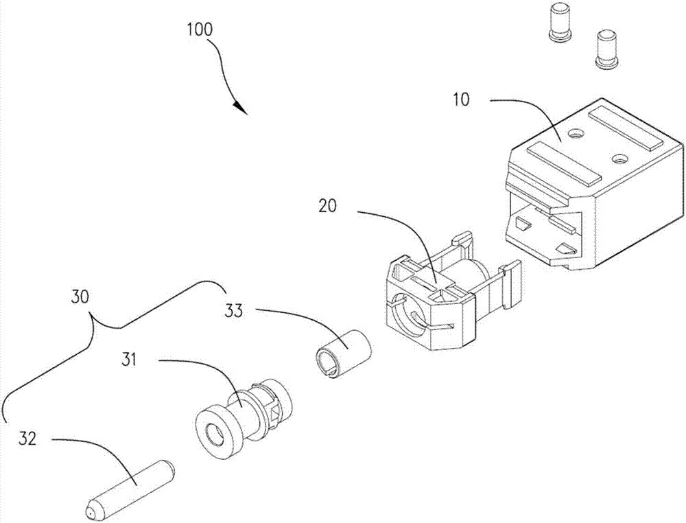
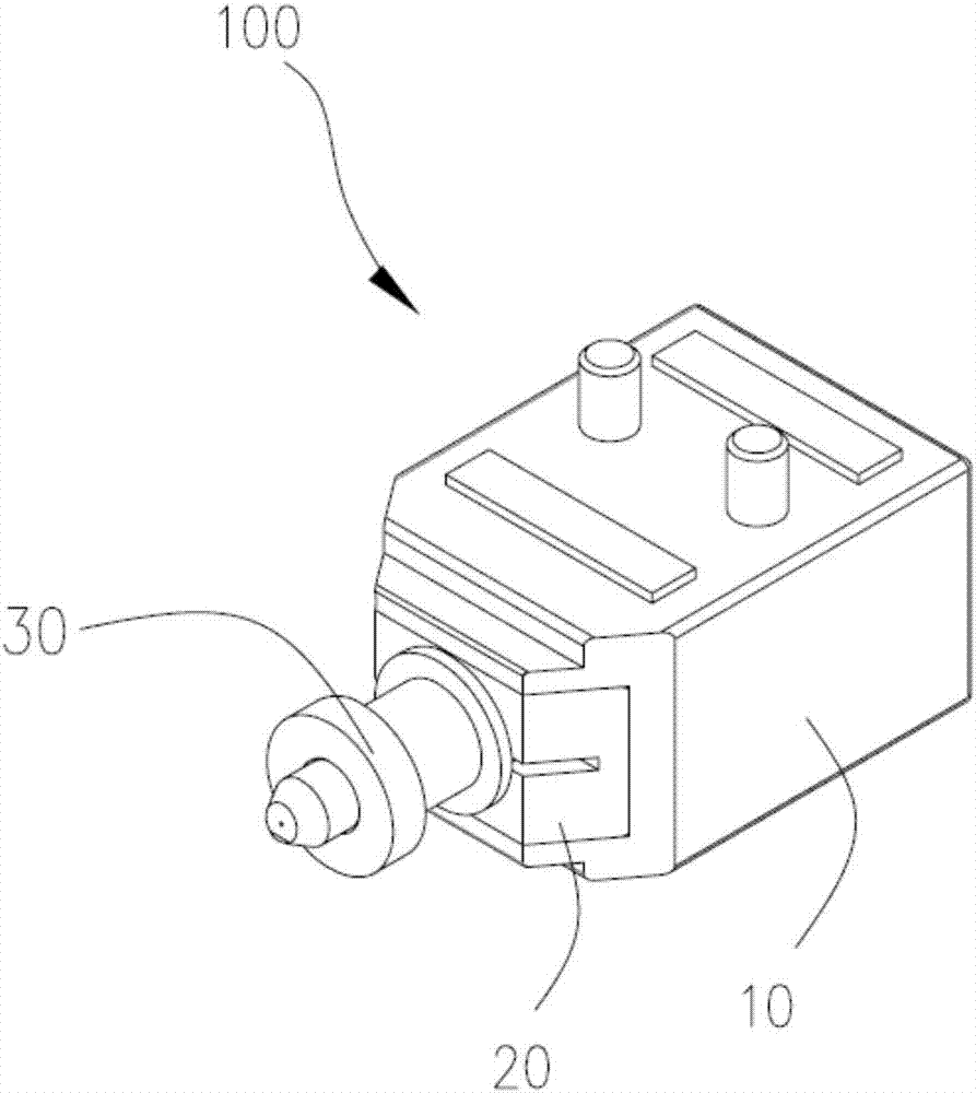
[0024] see figure 1 and figure 2 , the first embodiment of the present invention provides an optical interface 100 . The optical interface 100 is applied in an optical transceiver assembly to connect the body of the optical transceiver assembly with an external optical jumper. The optical interface 100 includes a housing 10 , a fixing buckle 20 and an adapter 30 . The adapter 30 includes a hollow metal piece 31 , a ferrule 32 and a sleeve 33 . The ferrule 32 i...


PUM


Abstract

The optical interface comprises a housing, a fixing buckle and an adapter. The adapter comprises a hollow metal member, an inserting core and a sleeving; the inserting core is arranged inside the metal member; a first end of the inserting core is projected out of the first end of the metal member; the sleeving is arranged on a second end of the inserting core which is opposite to the first end; the fixing buckle fixes the adapter in the housing; the first end of the inserting core and the first end of the metal member are arranged on outside of the housing; when the first end of the metal member is connected to the main body of the light transmit-receive assembly, the first end of the inserting core is received in the main body of the optical transmit-receive assembly; the sleeving sleeves the first end of the inserting core of an external optical jumper wire which projects into the housing in order to make the first end of the inserting core of the external optical jumper wire perform butt joint with the inserting core of the adapter. The optical interface of the invention is low in structure, simple in manufacture technology and low in cost, can improve production efficiency and can improve a market potential of the optical transmit-receive assembly using the optical interface. The invention also discloses an optical transmit-receive assembly.

Description

technical field [0001] The invention relates to the technical field of communication, in particular to an optical interface and an optical transceiver assembly. Background technique [0002] With fiber-to-the-home, "optical into copper and out" has become the development trend of broadband access network. The annual shipment of optical terminal products for access network has exceeded 10 million, and miniaturization and low cost have always been the key goals of products. The existing pigtailless optical transceiver component technology is the current stage of the technical evolution of access optical terminal products. The optical transceiver assembly at this stage includes a base, an optical transceiver assembly body, an adapter and an upper cover. Wherein, the adapter, the base and the upper cover constitute the optical interface of the optical transceiver assembly. Due to the complex manufacturing process of the adapter, two riveting processes are required, which makes...

Claims


Application Information

Patent Timeline
IPC IPC(8): G02B6/38H04B10/40G02B6/42
CPCG02B6/3807G02B6/42H04B10/40
Inventor 梁韬王立平
Owner HUAWEI MACHINERY
Why Eureka
Try Eureka