Protective gas device for laser processing

A laser processing and shielding gas technology, which is applied in laser welding equipment, metal processing equipment, manufacturing tools, etc., can solve the problems of unstable air flow, uneven gas volume on the processing surface, and protection of dead angles, so as to inhibit diffusion and avoid weld bead oxidation Effect

Pending Publication Date: 2017-11-14
ZHONGSHAN HANTONG LASER SCI
View PDF6 Cites 1 Cited by
  • Summary
  • Abstract
  • Description
  • Claims
  • Application Information

AI Technical Summary

Problems solved by technology

The existing protective gas device generally directly blows the protective gas from the side to the processing area through the blowing pipe, but this often results in uneven gas volume on the processing surface and protection dead angles, etc.
In this way, the air flow is unstable and the precision of the processed workpiece is not high.

Method used


Image

  • Protective gas device for laser processing
  • Protective gas device for laser processing
  • Protective gas device for laser processing

Examples


Embodiment Construction

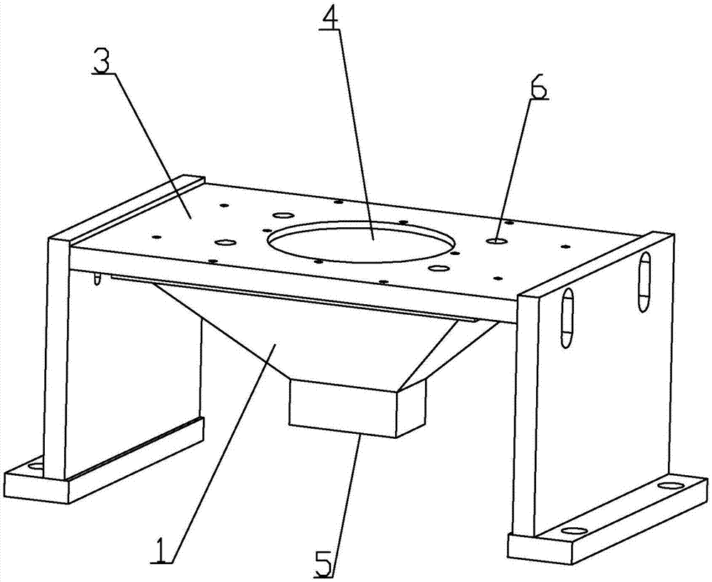
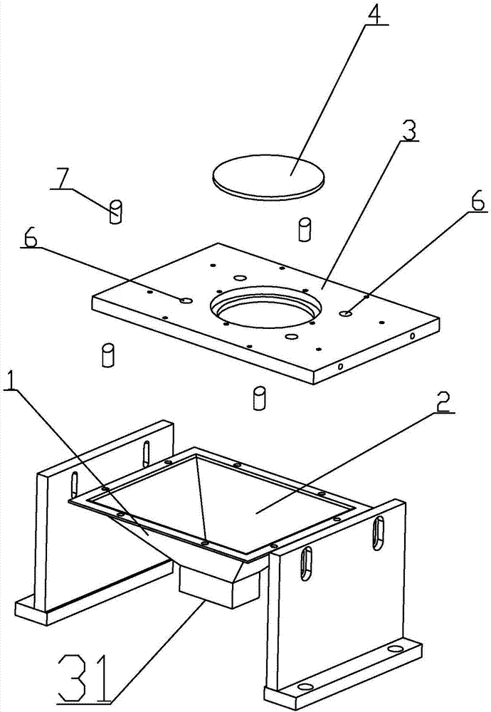
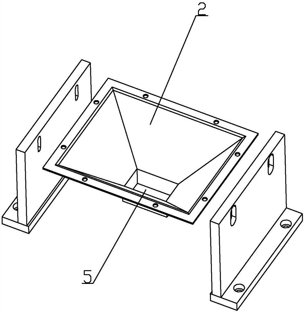
[0012] Below in conjunction with accompanying drawing and specific embodiment the present invention is described in further detail:

[0013] like Figure 1 to Figure 3 As shown, a shielding gas device for laser processing includes a housing 1. A shielding gas chamber 2 and a cover plate 3 for covering the shielding gas chamber 2 are arranged in the housing 1. The upper and lower ends of the shielding gas chamber 2 are opened, and the cover The plate 3 covers the upper opening of the protective gas cavity 2, the protective gas cavity 2 is an inverted conical cavity, and the cover plate 3 is provided with a lens 4 for the laser to penetrate into the protective gas cavity 2. By setting the lens 4, the Laser focus to reduce energy loss. The bottom of the protective gas chamber 2 is provided with an air outlet 5 aligned with the workpiece to ensure that the protective gas can effectively protect the workpiece, and the protective gas can evenly isolate the external air in the proce...


PUM


Abstract

The invention relates to a protective gas device for laser processing. The device comprises a shell; and a protective gas cavity and a cover plate for covering the upper end of the protective gas cavity are arranged in the shell. The device is characterized in that the protective gas cavity is an inverted conical cavity; the cover plate is provided with a lens for enabling laser to penetrate into the protective gas cavity; an exhaust port aligned to machined workpieces is formed in the bottom of the protective gas cavity; and the cover plate is provided with an intake port communicating with the protective gas cavity. The device is simple in structure and stable in airflow, and improves the laser welding quality.

Description

【Technical field】 [0001] The invention relates to a protective gas device for laser processing. 【Background technique】 [0002] In laser processing, in order to ensure the processing quality and prevent the weld bead on the surface of the workpiece from being oxidized and discolored after processing, a protective gas device is usually installed. The protective gas device is generally installed above the workpiece, and the gas outlet is aligned with the processing area. The protective gas is generally Inert gases such as helium etc. The existing protective gas device generally blows the protective gas from the side to the processing area directly through the blowing pipe, but this often results in uneven gas volume on the processing surface and protection dead angles. In this way, the air flow is unstable, and the precision of the processed workpiece is not high. 【Content of invention】 [0003] The purpose of the present invention is to overcome the deficiencies of the pr...

Claims


Application Information

Patent Timeline
Patent Type & Authority Applications(China)
IPC IPC(8): B23K26/14B23K26/21
CPCB23K26/14B23K26/21
Inventor 林晓聪郭明华车荣泓林康鎬蓝卓康陈冠华梅叶平王进宝雷新平谢志宏梁家辉
Owner ZHONGSHAN HANTONG LASER SCI
Why Eureka
Try Eureka