Novel multifunctional combined type Chinese bee beehive
A multi-functional and combined technology, applied in beehives, beekeeping, applications, etc., can solve the problems of difficult to increase the number of bee colonies and inconvenient transportation, and achieve the effect of increasing the number of bee colonies and reducing transportation
- Summary
- Abstract
- Description
- Claims
- Application Information
AI Technical Summary
Problems solved by technology
Method used
Image
Examples
Embodiment 1
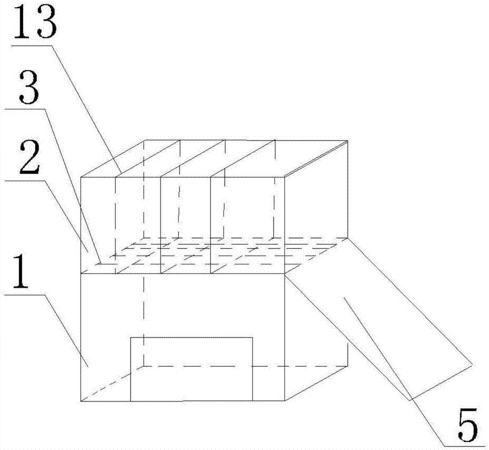
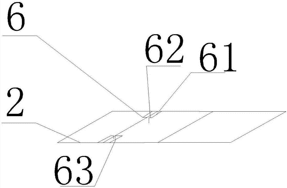
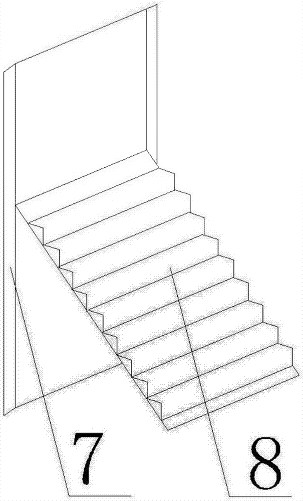
[0022] Such as figure 1 , figure 2 , image 3 , Figure 4 Shown, a kind of novel multi-functional combined middle bee beehive, comprises beehive 1, and the upper end of beehive 1 is provided with following box 2, and between beehive 1 and following box 2 is provided with partition board 3, and partition board 3 is formed by adjacent The spacing is 4.4mm grid bars, one side of the beehive 1 is provided with a slide plate 5 that can slide along the side of the beehive, and the two vertical ends of the side of the beehive 1 are provided with vertical plates perpendicular to the side, and the two vertical plates are connected to the side of the beehive. The side of beehive 1 forms U-shaped plate 7, and one end of slide plate 5 slides in U-shaped plate, and the other end of slide plate 5 is free end; Slide plate 5 is made up of a plurality of slide plate units 8 that can be folded into flat plates; There is a partition 13 inside, and the contact end between the partition 13 and...
Embodiment 2
[0030] The difference between this embodiment and Embodiment 1 is that first vertical plates 9 are provided at both ends of the sides of the slide plate 5 near the bottom of the beehive 1, and the two first vertical plates 9 form a U-shaped structure with the back of the slide plate 5 ; Hanging buckle 12, one end of spring member 4 is fixed on the slide bar 10, and the other end of spring member 4 can be hung on the hanging buckle 12.
[0031] In this embodiment, on the basis of Embodiment 1, the structure of the slide plate 5 is further optimized. A first vertical plate 9 is arranged at both ends of the back of the slide plate 5. There are two first vertical plates 9. The first vertical plate 9 and the back of the skateboard 5 form a U-shaped structure, and a sliding rod 10 is set on the U-shaped structure. The sliding rod 10 moves on the back of the skateboard 5, that is, when the skateboard 5 is stretched to a certain position, its position can be fixed. And the concrete f...
Embodiment 3
[0033] The difference between this embodiment and the above embodiments is that: the free end of the sliding plate 5 is provided with an extension plate 11 . The main effect of the setting of the extension plate 11 is that when the free end of the slide plate 5 is placed on a horizontal plane, the planar structure of the extension plate 11 is parallel to the ground to support the overall structure of the slide plate 5 and the like.
PUM
 Abstract
Description
Claims
Application Information
 - R&D
- Intellectual Property
- Life Sciences
- Materials
- Tech Scout
- Unparalleled Data Quality
- Higher Quality Content
- 60% Fewer Hallucinations
Browse by: Latest US Patents, China's latest patents, Technical Efficacy Thesaurus, Application Domain, Technology Topic, Popular Technical Reports.
© 2025 PatSnap. All rights reserved.Legal|Privacy policy|Modern Slavery Act Transparency Statement|Sitemap|About US| Contact US: help@patsnap.com


