Sludge preheating device and sludge drying system

A preheating device and sludge technology, applied in dehydration/drying/concentrated sludge treatment, energy wastewater treatment, etc., can solve the problems of energy waste, equipment without heat recovery and utilization, etc., to avoid water hammer and effectively reuse , The effect of minimizing energy consumption

Active Publication Date: 2017-11-17
NANJING CEC ENVIRONMENTAL ENGINEERING CO LTD
View PDF5 Cites 5 Cited by
  • Summary
  • Abstract
  • Description
  • Claims
  • Application Information

AI Technical Summary

Problems solved by technology

[0003] At present, the indirect drying process is the most widely used in the sludge drying treatment method, and the indirect drying process mostly adopts steam heating, and the primary steam pressure is generally around 0.6MPa. Part of the heat can be recycled, but there is no equipment to recycle this part of the heat, which causes a lot of energy waste

Method used


Image

  • Sludge preheating device and sludge drying system
  • Sludge preheating device and sludge drying system
  • Sludge preheating device and sludge drying system

Examples


Embodiment 1

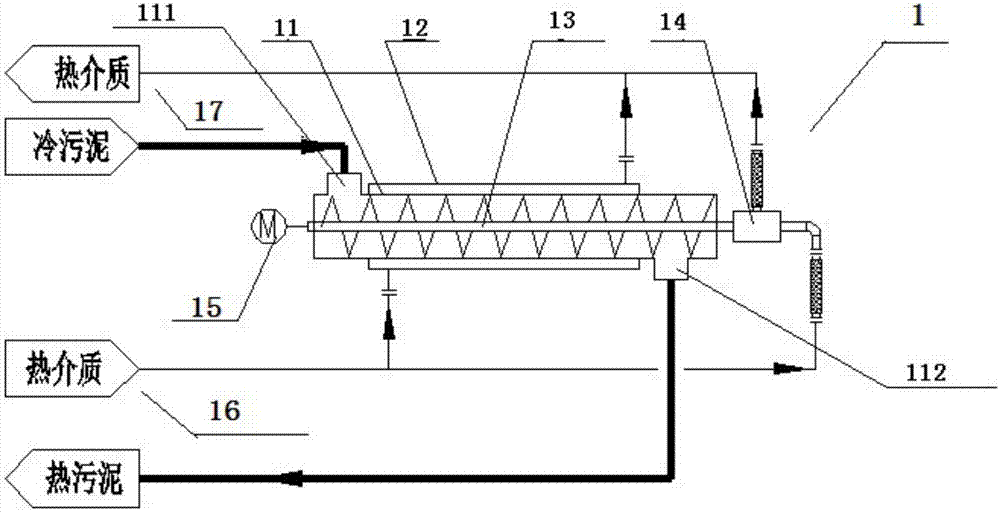
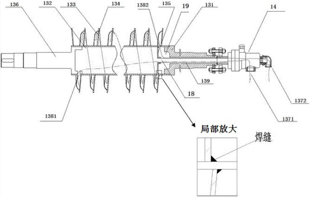
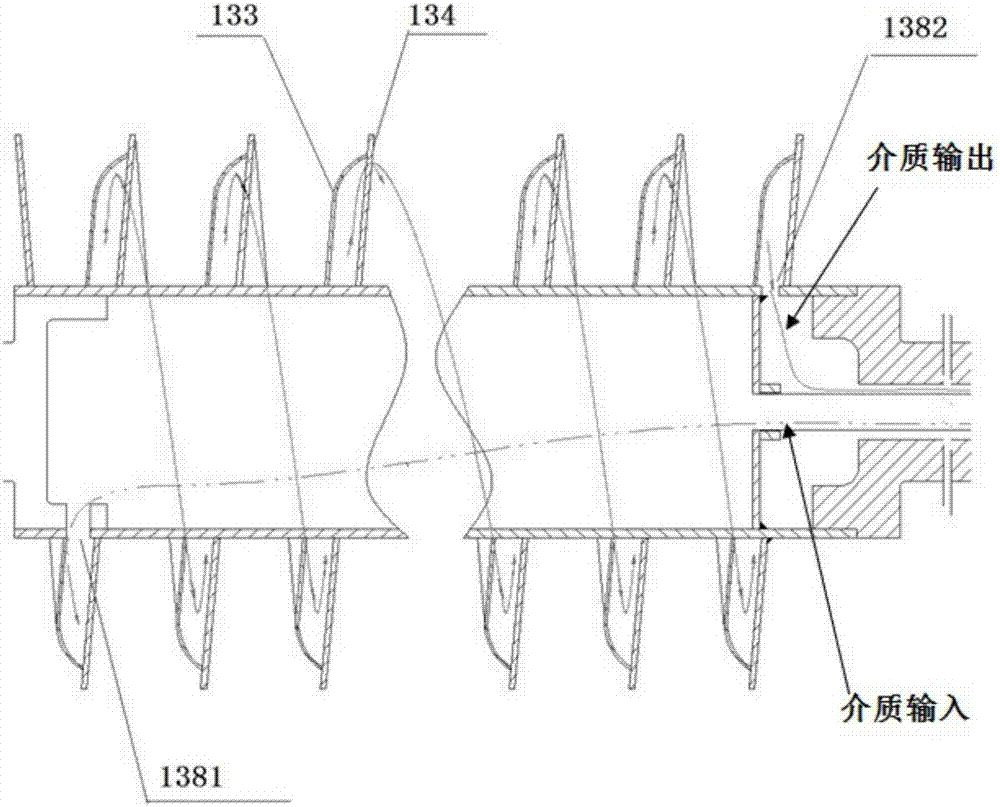
[0036] Such as Figure 1 to Figure 3 As shown, Embodiment 1 discloses a sludge preheater, that is, a hollow spiral sludge preheater 1 (abbreviated as a sludge preheater 1), which includes a housing 11 that sequentially accommodates the passage of sludge, and can be passed into The jacket 12 of the heat medium, the hollow screw shaft 13 that can pass through the medium to heat and push the sludge forward, connects the rotary joint 14 at one end of the hollow screw shaft 13; connects to the other end of the hollow screw shaft 13 and is used to drive the hollow screw shaft 13 rotating drive means 15.

[0037] The housing 11 is provided with a feed port 111 and a discharge port 112. The cold sludge entering the equipment through the feed port 111 is preheated and then comes out from the discharge port 112 to become hot sludge.

[0038] The jacket 12 is sleeved on the outside of the housing 11 and can be connected with the hollow screw shaft 13 and the medium input end 16 through ...

Embodiment 2

[0048] Embodiment 2 discloses a sludge drying system, which includes a sludge preheating device, a sludge drying device, and a heat recovery device.

[0049] Such as Figure 4 As shown, the sludge preheating device adopts the sludge preheater 1 with the structure shown in Example 1, and the cavity of the hollow screw shaft 13 can be fed with heat medium, which can realize material transportation and preheating at the same time.

[0050] The sludge drying device adopts an indirect indirect drying machine 2, and can choose a disc drying machine, a paddle drying machine or a thin layer drying machine and other types of indirect drying machines, which mainly include drying machines Body 21, material inlet 22, material outlet 23, steam trap 24, etc.

[0051] combine Figure 5 As shown, the heat energy recovery device can use a heat energy recovery device 3, which mainly includes a cylinder body 31, a flash steam outlet 32, a condensed water outlet 33, a cylinder body 33, a steam ...


PUM


Abstract

The invention provides a sludge preheating device. The sludge preheating device comprises a casing, a hollow screw shaft, a rotating joint and a driving device, wherein a feeding port and a discharging port are formed in the casing; the hollow screw shaft penetrates in the casing; the driving device is used for driving the hollow screw shaft to rotate; a hollow cavity structure capable of allowing thermal media to circulate is arranged in the hollow screw shaft, and the rotating joint is communicated with the hollow cavity structure in the hollow screw shaft to serve as a channel allowing the thermal media to enter or exit from the hollow screw shaft. Furthermore, the invention discloses a sludge drying system. The sludge drying system comprises the sludge preheating device, a sludge drying device and a thermal energy recovery device. Materials can be preheated and pushed by the aid of the sludge preheating device, and waste heat can be effectively reused by the aid of the sludge drying system, so that the energy consumption is minimized.

Description

technical field [0001] The invention relates to the technical field of sludge drying treatment, in particular to a sludge preheating device and a sludge drying system. Background technique [0002] With the development of the economy and the improvement of people's living standards, the process of urbanization is accelerating, the amount of industrial sewage and domestic sewage is increasing, and the amount of sludge generated is also increasing. At the same time, my country's industrial field is developing rapidly. The sludge discharge of pharmaceutical and chemical enterprises is increasing rapidly, and the resulting environmental pollution is becoming more and more serious. For this reason, the state strongly supports sludge reduction and incineration technology, among which drying technology has been greatly developed and applied. [0003] At present, the indirect drying process is the most widely used in the sludge drying treatment method, and the indirect drying proces...

Claims


Application Information

Patent Timeline
Patent Type & Authority Applications(China)
IPC IPC(8): C02F11/12
CPCC02F11/12Y02W10/30
Inventor 王世兴刘政艳曹志勇祁本武刘霄
Owner NANJING CEC ENVIRONMENTAL ENGINEERING CO LTD
Why Eureka
Try Eureka