
Traction type hydraulic driving water tank cutting machine and using method thereof

A sink cutting machine and traction type technology, applied in drainage, earthwork drilling, safety devices, etc., can solve problems such as affecting the later process, affecting the progress of the project, irregular shape of the water channel, etc., so as to facilitate the subsequent process and improve the work efficiency. , the effect of speeding up the progress of the project

Active Publication Date: 2017-11-17
LIAONING TECHNICAL UNIVERSITY
View PDF5 Cites 7 Cited by
  • Summary
  • Abstract
  • Description
  • Claims
  • Application Information

AI Technical Summary

Problems solved by technology

[0002] Before coal mining, in order to facilitate construction and improve mining efficiency, it was necessary to open a ditch on the ground of the roadway next to the coal wall to discharge the accumulated water in the underground roadway. The current methods are manual slotting, which is time-consuming and laborious, and affects the progress of the project. At the same time, the shape of the ditch created by manpower is irregular, which affects the later process and is not conducive to the discharge of water in the lane

Method used


Image

  • Traction type hydraulic driving water tank cutting machine and using method thereof
  • Traction type hydraulic driving water tank cutting machine and using method thereof
  • Traction type hydraulic driving water tank cutting machine and using method thereof

Examples


Embodiment Construction

[0024] The following will clearly and completely describe the technical solutions in the embodiments of the present invention with reference to the accompanying drawings in the embodiments of the present invention. Obviously, the described embodiments are only part of the embodiments of the present invention, not all of them. Based on the embodiments of the present invention, all other embodiments obtained by persons of ordinary skill in the art without creative efforts fall within the protection scope of the present invention.

[0025] It should be noted that all directional indications (such as up, down, left, right, front, back...) in the embodiments of the present invention are only used to explain the relationship between the components in a certain posture (as shown in the accompanying drawings). Relative positional relationship, movement conditions, etc., if the specific posture changes, the directional indication will also change accordingly. In addition, the descripti...


PUM


Abstract

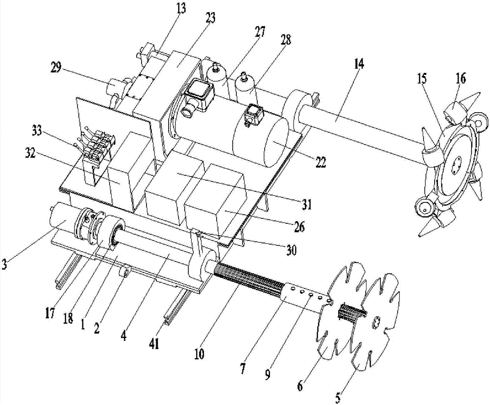
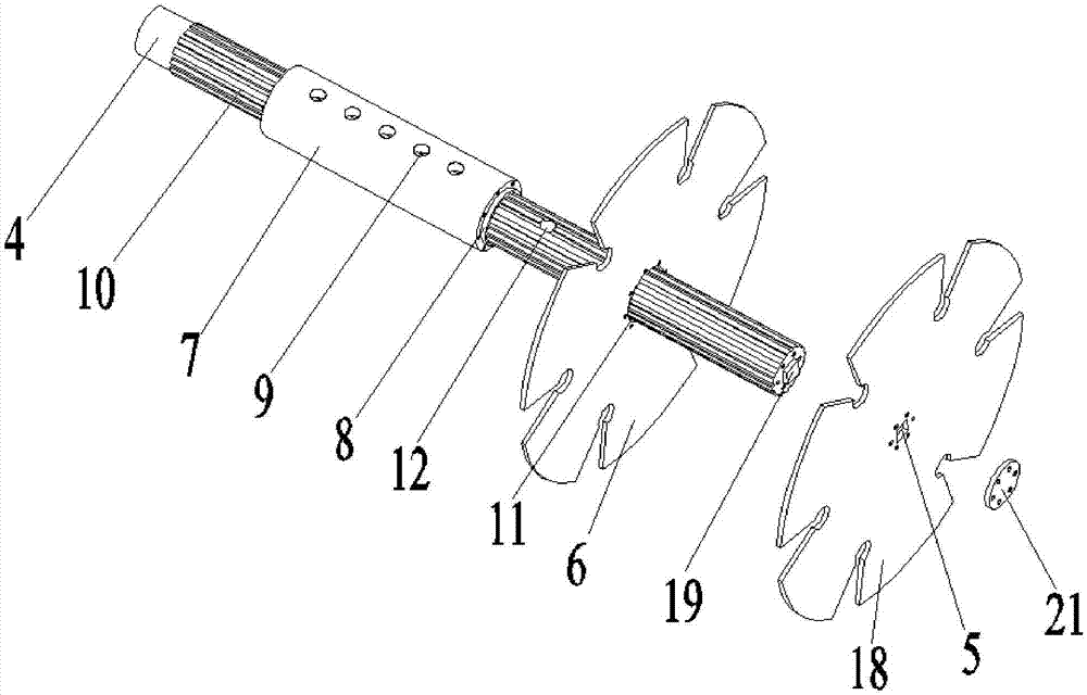
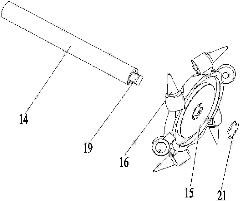
The invention discloses a traction type hydraulic driving water tank cutting machine and a using method thereof. The cutting machine comprises a frame; a first hydraulic motor and a second hydraulic motor are arranged on the frame; the output end of the first hydraulic motor is connected with a first drive shaft; a first cutting piece and a second cutting piece which are arranged in a spaced mode are fixed to the first drive shaft; and the output end of the second hydraulic motor is connected with a second drive shaft, a rotating disc is fixed to the second drive shaft, and a plurality of cutting teeth which are arranged by certain angles are arranged on the rotating disc. An electric motor is arranged on the frame; the output end of the electric motor is connected with a crank piston pump; the two sides of the crank piston pump are connected to an oil tank through a first double-valve body and a second double-valve body correspondingly; and an oil outlet of the crank piston pump is connected to oil inlets of the first hydraulic motor and the second hydraulic motor; and a travelling part is arranged at the bottom of the frame. Machines are adopted to replace manual work, the time and labor are saved, convenience and high efficiency are achieved, a water tank with the two level sides can be opened, the subsequent process is facilitated, the situation that accumulation water in a roadway is discharged in time is facilitated, the project progress is accelerated, and the work efficiency is improved.

Description

technical field [0001] The invention belongs to the technical field of coal and rock crushing, and in particular relates to a traction hydraulically driven water tank cutting machine and a use method thereof. Background technique [0002] Before coal mining, in order to facilitate construction and improve mining efficiency, it was necessary to open a ditch on the ground of the roadway next to the coal wall to discharge the accumulated water in the underground roadway. The current methods are manual slotting, which is time-consuming and laborious, and affects the progress of the project. At the same time, the shape of the ditch created by manpower is irregular, which affects the later process and is not conducive to the discharge of water in the lane. [0003] Therefore, it is necessary to design a mechanical slotting device to solve the above problems. Contents of the invention [0004] Aiming at the problems existing in the prior art, the present invention provides a tra...

Claims


Application Information

Patent Timeline
IPC IPC(8): E21F16/02B28D1/24
CPCB28D1/24E21F16/02
Inventor 张强刘永凤刘志恒孙绍安
Owner LIAONING TECHNICAL UNIVERSITY
Learn More