High-performance regulating valve with floating valve base

A floating valve seat, high-performance technology, used in valve devices, engine components, cocks including cut-off devices, etc. Rod flexibility and other issues, to achieve the effect of simple structure, good self-sealing performance and good sealing performance

Pending Publication Date: 2017-11-17
ZHEJIANG BEIER CONTROL VALVE
View PDF4 Cites 0 Cited by
  • Summary
  • Abstract
  • Description
  • Claims
  • Application Information

AI Technical Summary

Problems solved by technology

[0002] In the traditional regulating valve, the valve stem is fixedly connected with the valve plate. When the pressure in the valve body is high, the valve stem will be subjected to the scouring force of the medium, resulting in deformation and vibration, and the valve plate will be sealed with the deviation of the valve stem. If it is not strict, the accuracy and motion precision of the valve plate movement will deteriorate; more often, after the valve is assembled, the valve stem and the drive shaft of the actuator are usually not on the same axis, and there is a large error. When the valve stem is connected to the drive shaft After being fixed, the valve stem will have a certain deflection, which not only affects the flexibility of the valve stem itself, but also greatly affects the accuracy and precision of the valve core movement, which will eventually lead to poor sealing and leakage , short service life, troublesome maintenance operations, poor practicability

Method used


Image

  • High-performance regulating valve with floating valve base
  • High-performance regulating valve with floating valve base

Examples


Embodiment Construction

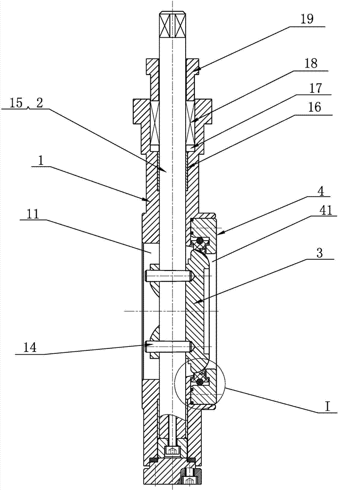
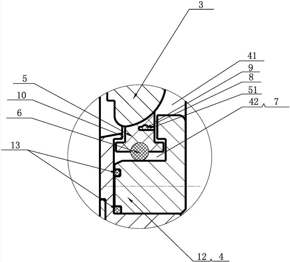
[0015] see figure 1 and figure 2 , a floating seat high-performance regulating valve disclosed in the present invention, comprising a valve body 1, a valve stem 2 and a valve plate 3, the valve body 1 is provided with a valve cavity 11, and the valve plate 3 is installed in the valve cavity 11 , the lower end of the valve stem 2 is inserted into the valve chamber 11, and the lower end of the valve stem 2 is detachably connected to the valve plate 3; one end of the valve body 1 is provided with a pressure plate installation groove 12, and a positioning plate is arranged in the pressure plate installation groove 12 Pressing plate 4, a medium through hole 41 is provided in the middle of the positioning pressing plate 4, a sealing seat installation groove 42 is provided on the inner wall surface of the medium through hole 41, and a sealing seat installation groove 42 is installed in the sealing seat installation groove 42 for connecting with the valve plate 3 A sealed floating s...


PUM


Abstract

The invention discloses a high-performance regulating valve with a floating valve base. The high-performance regulating valve comprises a valve body, a valve rod and a valve plate, wherein a press plate installing groove is formed in one end of the valve body, a positioning press plate is arranged in the press plate installing groove, a medium through hole is formed in the middle of the positioning press plate, a seal seat installing groove is formed in the inner wall face of the medium through hole, a floating seal seat for sealing the valve plate is installed in the seal seat installing groove, a first seal ring is arranged at the end, deviating from the valve plate, of the floating seal seat, a first regulating gap is reserved between the first seal ring and the inner wall face of the seal seat installing groove, and the floating seal seat radially floats in the first regulating gap. A self-seal structure is arranged on the floating seal seat. By adopting the technical scheme, the high-performance regulating valve is reasonable in structural design, simple in structure, good in sealing performance, not prone to leakage, long in service life, easy to operate and maintain and high in practicability.

Description

technical field [0001] The invention relates to the technical field of valves, in particular to a high-performance regulating valve with a floating valve seat. Background technique [0002] In the traditional regulating valve, the valve stem is fixedly connected with the valve plate. When the pressure in the valve body is high, the valve stem will be subjected to the scouring force of the medium, resulting in deformation and vibration, and the valve plate will be sealed with the deviation of the valve stem. If it is not strict, the accuracy and motion precision of the valve plate movement will deteriorate; more often, the valve stem and the drive shaft of the actuator are usually not on the same axis after the valve is assembled, and there is a large error. When the valve stem is connected to the drive shaft After being fixed, the valve stem will have a certain deflection, which not only affects the flexibility of the valve stem itself, but also greatly affects the accuracy ...

Claims


Application Information

Patent Timeline
Patent Type & Authority Applications(China)
IPC IPC(8): F16K5/06
CPCF16K5/0673
Inventor 林童林峰王平红郑博黄真伟邱晨洁
Owner ZHEJIANG BEIER CONTROL VALVE
Why Eureka
Try Eureka