A composite measuring device for airflow velocity and temperature for low-speed flow field

A technology of airflow velocity and measuring device, which is applied to measuring devices, instruments, etc., can solve the problems of harsh working environment of measuring instruments, affecting the normal progress of measuring process, and uncertainty of airflow direction of measuring points, etc. , simple layout effect

Active Publication Date: 2019-12-31
TONGJI UNIV
View PDF6 Cites 0 Cited by
  • Summary
  • Abstract
  • Description
  • Claims
  • Application Information

AI Technical Summary

Problems solved by technology

Among them, when the pitot tube and the impeller measure the airflow velocity, they are sensitive to the direction of the airflow. It is necessary to make the arrangement direction of the pitot tube or the impeller completely consistent with the direction of the incoming flow to ensure the accuracy of the measurement, and it is affected by the size of the pitot tube and the diameter of the impeller. However, when the thermocouple measures the airflow temperature, the thermocouple must be firmly fixed on the measurement point. If the thermocouple is directly fixed to a certain part in the car, it will not only fix the It is more difficult, and it will also affect the normal work of various systems in the car
When it is necessary to simultaneously measure the speed and temperature of the airflow in a small space (such as before and after the radiator of a car), the existing measurement methods have obvious limitations: one is that the airflow is affected by the air intake grille, condenser and cooling fan , it will become uneven, making the airflow direction of the measuring point uncertain and affecting the accuracy of the measurement; second, the distance between the condenser and the radiator is usually less than 20mm, which is not conducive to the layout of the measuring instrument; third, some parts ( Such as radiators, three-way catalytic converters, etc.) The temperature is high, which makes the working environment of the measuring instrument too harsh and affects the normal progress of the measurement process.

Method used


Image

  • A composite measuring device for airflow velocity and temperature for low-speed flow field
  • A composite measuring device for airflow velocity and temperature for low-speed flow field
  • A composite measuring device for airflow velocity and temperature for low-speed flow field

Examples


Embodiment

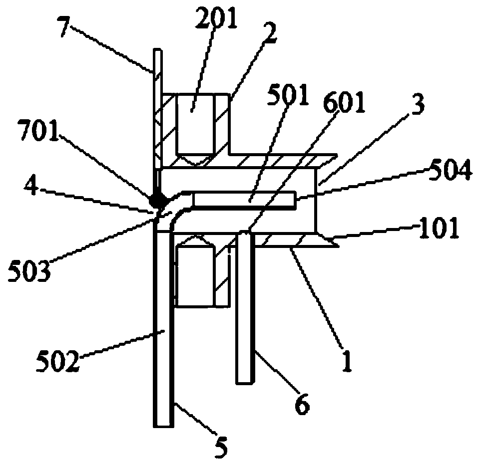
[0031] Such as figure 1 Shown is an airflow velocity and temperature composite measuring device for low-speed flow field, the device includes a wind deflector hood 1, a connecting arm 2 fixedly arranged on the wind deflector hood 1, and a The total pressure pipe 5 and the static pressure pipe 6 connected to the inside of the air diversion hood 1 are respectively connected to each other. The two ends of the air diversion hood 1 are respectively provided with an air inlet 3 and an air outlet of the air diversion hood. 4. A thermocouple 7 is provided at the air outlet 4 of the air diversion hood.

[0032] Wherein, the wind deflector 1 is hollow cylindrical, the connecting arm 2 is fixedly arranged on the outer wall of the wind deflector 1 , and the thermocouple 7 is fixedly connected with the connecting arm 2 . One end of the wind deflector 1 located at the air inlet 3 of the wind deflector is provided with a flow guide part 101 of the wind deflector 101 . One end of the connec...


PUM


Abstract

The invention relates to an air flow velocity and temperature composite measuring device for a low velocity flow field. The device comprises a wind deflector, a connecting support arm fixedly arranged on the wind deflector, and a total pressure pipe and a static pressure pipe which are arranged on the wind deflector and respectively connected with the inside of the wind deflector. Two ends of the wind deflector are provided with a wind deflector air inlet and a wind deflector air outlet respectively. A thermocouple is arranged at the wind deflector air outlet. Compared with the prior art, the device of the invention ensures that the direction of the total pressure pipe is consistent with the direction of an incoming flow and reduces the sensitivity to the incoming flow by the arrangement of the wind deflector hood; and the device has a compact size, can measure the air flow velocity and temperature of a low velocity field simultaneously in a region with a small space and complicated flow, is high in environmental adaptability, accurate in measurement, high in stability and small in disturbance to the flow field, avoids the interference to the measured region during the measurement, can be installed separately and also be assembled through a threaded rod into a measurement array, and is simple in layout and high in flexibility.

Description

technical field [0001] The invention belongs to the technical field of airflow measurement, and relates to an airflow velocity and temperature composite measurement device for low-speed flow field. Background technique [0002] In recent years, my country's auto industry has developed rapidly. The production and sales volume of automobiles has already surpassed that of the United States and Japan, ranking first in the world for eight consecutive years. With the continuous development of the automobile industry, the country has higher and higher requirements for automobiles in terms of fuel economy and emission levels. At the same time, consumers are paying more and more attention to automobile performance and comfort. Enterprises have invested a lot of manpower and material resources in research on engine thermal management, air-conditioning performance, body aerodynamics, and aerodynamic noise. In the course of these studies, it is indispensable to obtain velocity and temp...

Claims


Application Information

Patent Timeline
Patent Type & Authority Patents(China)
IPC IPC(8): G01D21/02
CPCG01D21/02
Inventor 王建新庞加斌刘晓辉李田田
Owner TONGJI UNIV
Why Eureka
Try Eureka