
UWB Microstrip Bandpass Filter

A band-pass filter and low-pass filter technology, which is applied in the field of communication devices, can solve the problems of narrow stopband and insufficient out-of-band suppression, and achieve the effects of small insertion loss, compact structure, and stopband bandwidth.

Active Publication Date: 2020-10-02
桂林恒毅金宇通信技术有限公司
View PDF13 Cites 0 Cited by
  • Summary
  • Abstract
  • Description
  • Claims
  • Application Information

AI Technical Summary

Problems solved by technology

Literature [5] introduced the construction of ultra-wideband filters by connecting open and short stub lines in parallel. This method has a simple structure, but its out-of-band suppression is not enough and the stop band is narrow

Method used


Image

  • UWB Microstrip Bandpass Filter
  • UWB Microstrip Bandpass Filter
  • UWB Microstrip Bandpass Filter

Examples


Embodiment Construction

[0010] An optimized specific embodiment is given below to describe the technical solution of the present invention and the beneficial effects obtained.

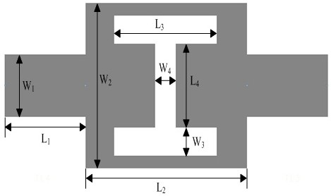
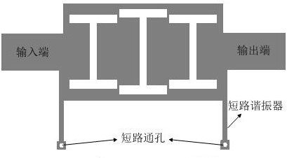
[0011] Such as figure 1 shown. L 1 , W 1 are the length and width of the microstrip line at the input and output ports, respectively, L 2 , W 2 are the length and width of the microstrip line to be etched, respectively, L 3 , W 3 Respectively, the length and width of the upper and lower groove lines of the etched H-shaped groove line, L 4 , W 4 are the length and width of the middle groove, respectively. The present invention adopts the cascading mode of three DMS structures to obtain a low-pass filter with a cut-off frequency of 10.6 GHz and a stop band width greater than 7 GHz. Its structure is as follows figure 2 shown. Cascading three DMS structure cascaded low-pass filters with a quarter-wavelength terminal short-circuit resonator, specifically adding terminal short-circuit resonators to the 50Ω microstrip lin...


PUM


Abstract

The invention discloses an ultra-wideband microstrip band-pass filter. The band-pass filter comprises a low-pass filter which is formed through the cascade connection of three H-shaped defected micro-strip structures. A quarter-wavelength terminal short-circuit resonator is added respectively to micro-strip lines at the input and output ports of the low-pass filter. According to the invention, the relative bandwidth of the band-pass filter is 116%, and the -20dB high frequency stop-band of the band-pass filter is up to 7 GHz. Compared with other technical schemes in the prior art, corresponding data are much wider, while the size is smaller than those of other existing technical schemes. The ultra-wideband microstrip band-pass filter has the advantages of good overall performance, compact structure, small insertion loss, wide stop-band and the like. The ultra-wideband microstrip band-pass filter is very suitable for the design of high-density monolithic microwave integrated circuits.

Description

technical field [0001] The invention relates to a communication device, in particular to an ultra-wideband microstrip bandpass filter. Background technique [0002] Ultra-wideband filters, as an indispensable device for establishing ultra-wideband circuits and systems, are developing very rapidly. In order to design filters with miniaturization, low insertion loss, and wide stopband, developers have conducted a lot of research [1-6]. Document [1] discloses that a low-pass filter and a high-pass filter are cascaded to realize band-pass filtering. The out-of-band suppression of this filter is better, but its structure is complex and its size is large, which is not convenient for design and integration. Literature [2-4] adopts branch loading and parallel coupling line structure to form an ultra-wideband filter, which has small insertion loss in the passband and good performance in the stopband, but its size is relatively large. Literature [5] introduces an ultra-wideband filt...

Claims


Application Information

Patent Timeline
Patent Type & Authority Patents(China)
IPC IPC(8): H01P1/203
CPCH01P1/20354
Inventor 蔡超波宋树祥袁伟强王斌王宜瑜胡文灿
Owner 桂林恒毅金宇通信技术有限公司
Learn More