Method and device for data transmission

A technology for transmitting data and sending data, which is applied in the field of data transmission, can solve problems such as no choice, and achieve the effect of reasonable utilization

Active Publication Date: 2017-11-17
ZTE CORP
View PDF6 Cites 22 Cited by
  • Summary
  • Abstract
  • Description
  • Claims
  • Application Information

AI Technical Summary

Problems solved by technology

If the base station does not choose beam A to transmit data, then the terminal still assumes beam a to receive, which is unreasonable
In a more reliable situation, the base station only uses the optimal downlink transmission beam reported by the terminal as a reference. The actual implementation may not select the optimal beam transmission from his

Method used


Image

  • Method and device for data transmission
  • Method and device for data transmission
  • Method and device for data transmission

Examples


Embodiment 1

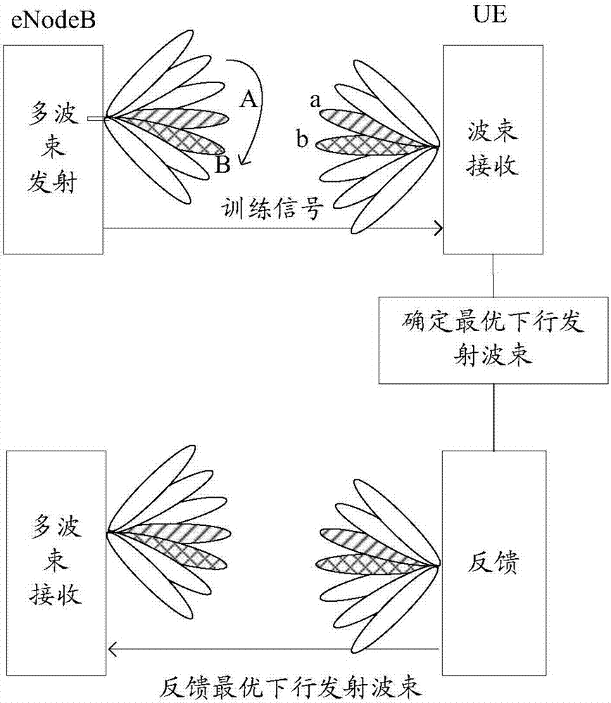
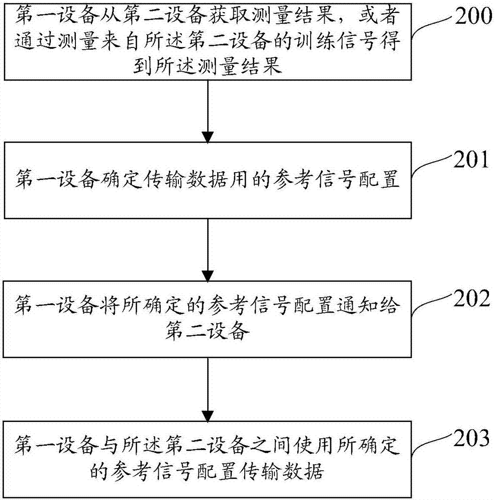
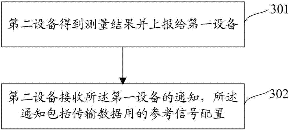
[0106] In this embodiment, the base station notifies the downlink optimized transmission beam to the terminal, so that the terminal can know the change of the transmission beam of the base station in time. Such as Figure 5 As shown, the method flow of this embodiment may include:

[0107] Step 501, the base station (eNodeB) transmits a training signal in each downlink transmission beam direction, and the training signal can be a synchronization signal, a discovery signal, a common pilot signal, etc.;

[0108] Step 502, the terminal (UE) determines the preferred beam set and feeds it back to the base station;

[0109] Wherein, the terminal receives the training signal, measures the training signal, selects one or several downlink transmission beams with the best reception quality and better according to the measurement results to form a preferred beam set, and feeds back the preferred beam set to the base station ; The best reception quality is the best reception quality, an...

Embodiment 2

[0125] Similar to downlink beam training, the terminal's uplink transmit beam also needs to be trained. In this embodiment, the situation that the base station notifies the uplink optimized transmit beam will be described in detail. Such as Figure 6 As shown, the method flow of this embodiment may include:

[0126] Step 601, the terminal transmits a training signal in each uplink transmit beam direction, and the training signal may be a random access signal, a channel sounding reference signal (Sounding Reference Signal, SRS), an uplink demodulation reference signal, etc.;

[0127] Step 602, the base station measures the training signal and obtains a preferred beam set;

[0128] Step 603, the base station selects an optimized uplink transmission beam for data transmission in the preferred beam set according to the load balancing between beams, interference suppression, and beam prediction algorithm under moving conditions, etc., and notifies the terminal, and the terminal r...

Embodiment 3

[0138] In this embodiment, the situation that the terminal notifies the uplink optimized transmit beam will be described in detail. Such as Figure 7 As shown, the method flow of this embodiment may include:

[0139] Step 701, the terminal transmits a training signal in each uplink transmission beam direction, and the training signal may be a random access signal, SRS, uplink demodulation reference signal, etc.;

[0140] Step 702, the base station measures and obtains the optimal uplink transmit beam set;

[0141] Step 703, the base station feeds back the optimal uplink transmit beam set to the terminal;

[0142] Step 704, the terminal selects an optimized uplink transmit beam for data transmission from the set of optimal uplink transmit beams, and notifies the base station of the reference signal configuration of the uplink transmit beam through uplink signaling;

[0143] In special cases, the terminal may also select a non-transmission beam identifier or a beam in the ind...


PUM


Abstract

The present invention discloses a method and device for data transmission. The method comprises: a first device determines configuration of reference signals for data transmission; the first device notice the determined configuration of the reference signals to a second device, wherein the reference signals are configured as the configuration of the reference signals of a wave beam, antenna port or a sector, the wave beam is an emission wave beam and/or receiving wave beam selected by the first device for data transmission, the antenna port is an antenna port selected by the first device for data transmission, and the sector is a sector selected by the first device for data transmission. The method and device provided by the invention allow the dual-way devices of data transmission to more reasonably utilize wireless energy to transmit data so as to improve the rate of data transmission and avoid transmission faults.

Description

technical field [0001] The present invention relates to the field of wireless communication, in particular to a method and device for transmitting data. Background technique [0002] The new generation of mobile communication systems will carry out system networking on carrier frequencies higher than those used by 2G, 3G, and 4G systems. Currently, the frequency bands that have been widely agreed in the industry and recognized by international organizations are mainly 3GHz-6GHz and 6GHz-100GHz. The first frequency band basically belongs to the centimeter wave band and the millimeter wave band, and its propagation characteristics are obviously different from those of the lower frequency band. Since the propagation loss of the high frequency band is significantly greater than that of the low frequency band, the coverage of the high frequency band is generally much smaller than that of the low frequency band. In order to enhance the coverage of high-frequency bands, beamforming...

Claims


Application Information

Patent Timeline
IPC IPC(8): H04W72/04H04W72/08
CPCH04W72/046H04W24/10H04W72/20H04W72/542H04W72/04
Inventor 张峻峰郝鹏鲁照华刘星
Owner ZTE CORP
Why Eureka
Try Eureka