A built-in vibrating magnetic separator

A technology of magnetic separator and vibrating motor, which is applied in the direction of magnetic separation, solid separation, cleaning method using liquid, etc. It can solve the problems such as the inability to adjust the position and amplitude of the media box, the high blocking rate of the media box, and the high power of the motor, etc., to achieve Effects of avoiding clogging, reducing weight, and enhancing reliability

Active Publication Date: 2019-01-15
HUBEI XINYING ENVIRONMENTAL TECH
View PDF9 Cites 0 Cited by
  • Summary
  • Abstract
  • Description
  • Claims
  • Application Information

AI Technical Summary

Problems solved by technology

[0003] The purpose of the present invention is to solve the problem of using leather tube connection in the prior art, which has complex structure, poor reliability, heavy vibration weight, high motor power, low vibration intensity, poor effect, high blockage rate of the medium box, and the position and amplitude of the medium box cannot be adjusted. problem, providing a built-in vibrating magnetic separator

Method used


Image

  • A built-in vibrating magnetic separator
  • A built-in vibrating magnetic separator

Examples


Embodiment Construction

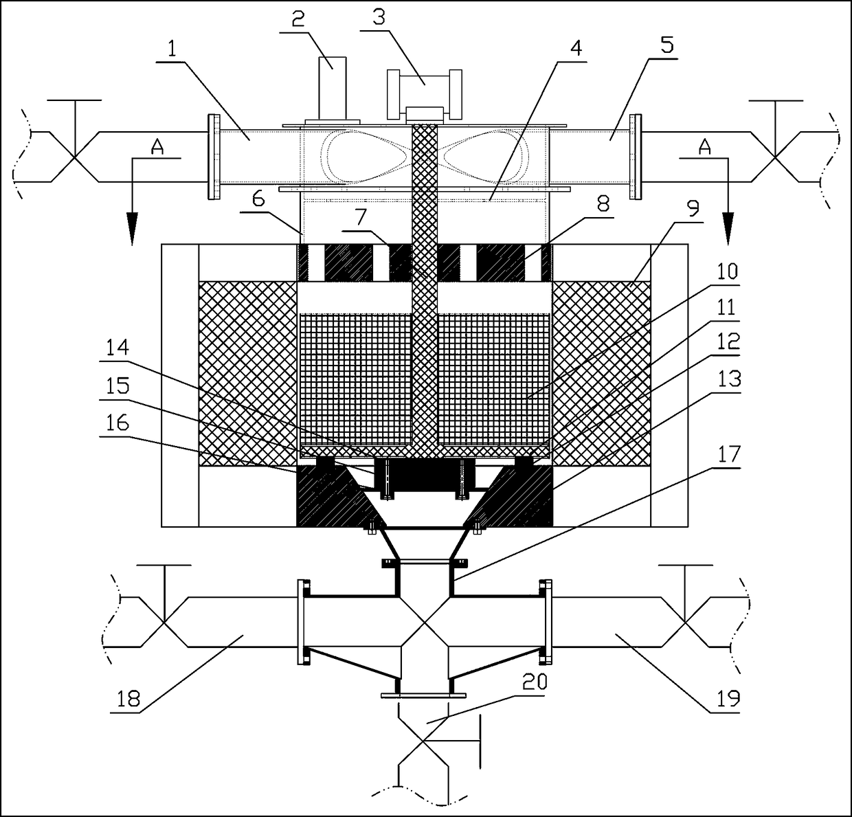
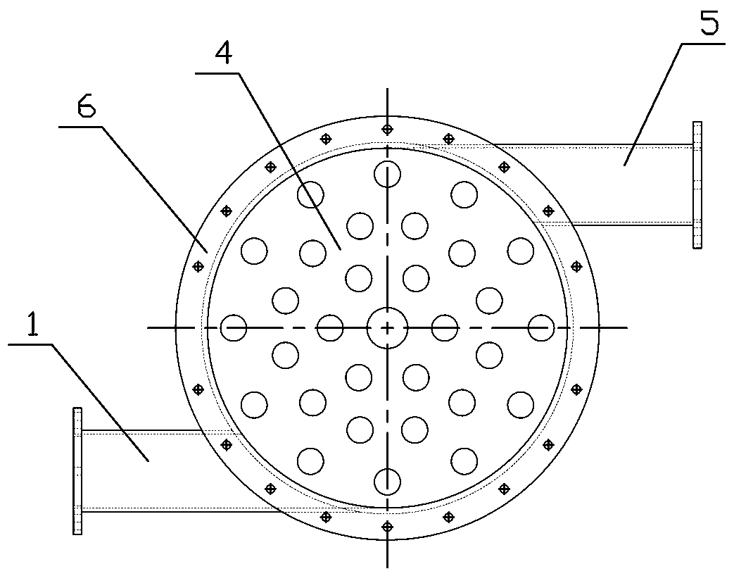
[0012] see Figure 1-2 , the present embodiment has a hollow casing 6, the top of the casing 6 is equipped with an exhaust pipe 2, the top of the casing 6 is provided with a feed pipe 1 and a water inlet pipe 5 communicating with the casing 6, and the inside of the casing 6 is from Screening net 4, upper magnetic pole 8 with several through holes, medium box 10, medium box base 11 and lower magnetic pole 13 are installed in order from top to bottom, and excitation coil 9 is installed in the upper and lower magnetic pole areas outside the housing 6. The middle part of the magnetic pole 13 is provided with a slag discharge hole, and a vibrating motor 3 is also installed above the housing 6, and the vibrating motor 3 is connected with the vibrating transmission shaft 7, and the vibrating transmission shaft 7 passes through the screen 4 and the upper magnetic pole in turn. 8. The medium box 10, the end of the vibration transmission shaft 7 is fixed on the medium box base 11, the s...


PUM


Abstract

The invention relates to the technical field of the non-metallic ore deironing equipment and in particular to a built-in vibration magnetic separator. The built-in vibration magnetic separator comprises a hollow housing. An exhaust pipe is installed above the housing. The top of the housing is provided with a feeding pipe and a water inlet pipe. The interior of the housing is successively provided with a sieving net, an upper magnetic pole with a plurality of through holes, a medium box, a medium box base, and a lower magnetic pole from top to bottom. The exterior of the housing is provided with an exciting coil within the upper and lower magnetic pole area. The middle part of the lower magnetic pole is provided with a slag discharge hole. The built-in vibration magnetic separator is characterized in that a vibration motor is further installed above the housing. The vibration motor is connected with a vibration transmission shaft. The vibration transmission shaft successively passes through the sieving net, the upper magnetic pole, and the medium box. The tail end of the vibration transmission shaft is fixed on the medium box base. The sum of the heights of the medium box and the medium box base is less than the distance between the upper and lower magnetic poles, so that the medium box can be upwards and downwards vibrated between the upper and lower magnetic poles. A four-way pipeline communicated with the slag discharge hole is installed below the lower magnetic pole. The built-in vibration magnetic separator is suitable for improving the current deironing equipment.

Description

technical field [0001] The invention relates to the field of non-metallic ore iron removal equipment, in particular to a built-in vibrating magnetic separator. Background technique [0002] At present, the mining industry usually adopts the vibration magnetic separation method when removing iron from non-metallic ores. First, the iron in the ore is adsorbed in the media box by power-on and magnetization, and then the power is demagnetized, and then the iron adsorbed in the media box is removed by vibration cleaning. For slag discharge, the vibrating magnetic separation equipment of the existing structure has two vibrating motors symmetrically installed on the side wall of the shell. When vibrating, in addition to the vibrating medium box, it also drives the shell of the entire equipment, the upper and lower magnetic poles, and the excitation coil to vibrate together. , the movable part and the fixed part are connected by a spherical soft leather tube, so the prior art has th...

Claims


Application Information

Patent Timeline
Patent Type & Authority Patents(China)
IPC IPC(8): B03C1/30B03C1/02B08B3/10B08B3/02
CPCB03C1/02B03C1/30B08B3/02B08B3/10
Inventor 瞿小文梅求文熊剑洪镇波殷浩东
Owner HUBEI XINYING ENVIRONMENTAL TECH
Why Eureka
Try Eureka