
Double-inclined hole machining device for numerical control machining center

A processing device and processing center technology, applied in the direction of positioning devices, clamping devices, metal processing equipment, etc., can solve the problems of unguaranteed drilling angle and processing accuracy, and required distance, etc., to achieve convenient operation, labor saving, drilling The effect of reducing the time for hole processing and ensuring distance accuracy

Pending Publication Date: 2017-11-21
SUZHOU QUNZHI MACHINERY EQUIP CO LTD
View PDF10 Cites 10 Cited by
  • Summary
  • Abstract
  • Description
  • Claims
  • Application Information

AI Technical Summary

Problems solved by technology

[0004] At present, when the shaft parts are processed in the CNC machining center, drilling machines are mostly used for drilling, but the existing drilling machines can only perform horizontal or vertical drilling on the shaft parts, and when processing There are two inclined holes with the same inclination angle, and the distance between the two inclined holes is also required. However, there is no such special punching device in the existing CNC machining center, so that the angle of punching and the accuracy of machining cannot be guaranteed. This brings many problems to the actual processing

Method used


Image

  • Double-inclined hole machining device for numerical control machining center
  • Double-inclined hole machining device for numerical control machining center
  • Double-inclined hole machining device for numerical control machining center

Examples


Embodiment Construction

[0017] The present invention will be further described in detail below in conjunction with the accompanying drawings and specific embodiments.

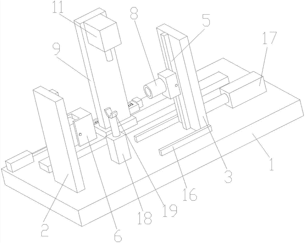
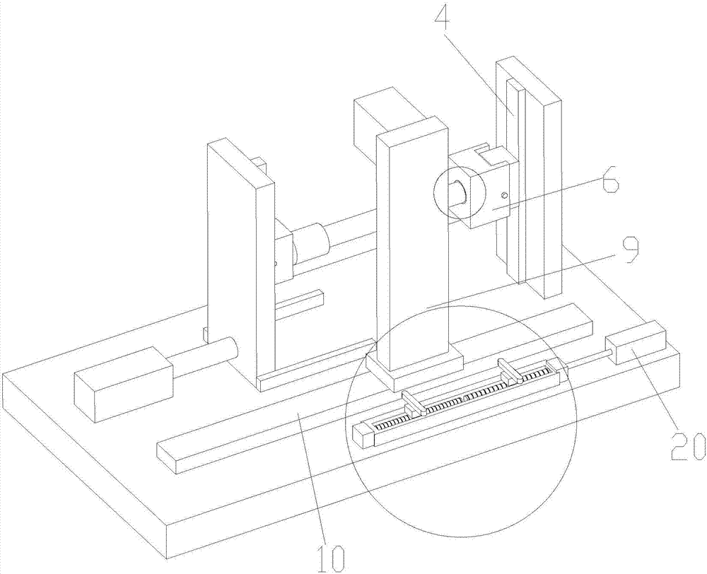
[0018] as attached Figure 1-4 The shown double slant hole processing device for a CNC machining center of the present invention includes a base 1, a first support plate 2, a second support plate 3, a first slide rail 4, a second slide rail 5, a rotating Block 6, electromagnet ring 7, positioning pipe 8, support assembly, drilling base 9, moving guide rail 10, drilling mechanism 11, measuring seat 12, screw mandrel 13, proximity switch 14 and motor 15; The first support plate 2 and the second support plate 3 are arranged oppositely, and the second support plate 3 is slidably arranged on the base 1; the first support plate 2 and the second support plate 3 are respectively provided with There are a first slide rail 4 and a second slide rail 5; the slider of the first slide rail 4 is provided with a rotatable rotating block 5; the rotat...


PUM


Abstract

The invention relates to a double-inclined hole machining device for a numerical control machining center. A first support plate and a second support plate are arranged on a base; the second support plate is glidingly arranged on the base; a first sliding rail and a second sliding rail are arranged on the first support plate and the second support plate; a rotatable rotation block is arranged on a sliding block of the first sliding rail; an accommodating slot is formed in the rotation block; an electromagnetic iron ring is arranged in the accommodating slot; a positioning tube is arranged on the second sliding rail; a positioning slot is formed in the positioning tube; a support component is arranged between the first support plate and the second support plate; a drilling base capable of moving transversely is arranged on one side of the support component; a drilling mechanism capable of moving up and down is arranged on the drilling base; a measuring base capable of moving transversely is arranged on one side of the drilling base; scales are arranged on the measuring base; a groove is formed in the measuring base; two symmetrically distributed screw rods are arranged in the groove, and are connected with a motor; a proximity switch is arranged at the upper end of the screw rod. The device provided by the invention can drill out inclined holes with the same inclination angle, and the space between two inclined holes can also be guaranteed.

Description

technical field [0001] The invention relates to a double inclined hole processing device, in particular to a double inclined hole processing device for a numerical control machining center. Background technique [0002] CNC machining center is a high-efficiency automatic machine tool suitable for processing complex parts composed of mechanical equipment and numerical control system. CNC machining centers are currently one of the most productive and widely used CNC machine tools in the world. It has strong comprehensive processing ability and is widely used in various fields. [0003] The shaft is a cylindrical object that goes through the middle of the bearing or the middle of the wheel or the middle of the gear, but a small part is also square. A shaft is a mechanical part that supports and revolves with a rotating part to transmit motion, torque or bending moment. [0004] At present, when the shaft parts are processed in the CNC machining center, drilling machines are ...

Claims


Application Information

Patent Timeline
IPC IPC(8): B23B41/00B23Q3/00B23Q3/154B23Q17/22
CPCB23B41/00B23Q3/00B23Q3/1543B23Q17/2233B23Q2703/10B23Q2703/04
Inventor 叶建根
Owner SUZHOU QUNZHI MACHINERY EQUIP CO LTD
Learn More