

Continuous flow vertical plane type liquid phase shearing device
A shearing device, planar technology, applied in the direction of nano-carbon, graphene, molybdenum sulfide, etc., can solve the problems of low energy, limited production rate, high stability requirements of power consumption devices, etc.
Active Publication Date: 2019-10-01
NANTONG UNIVERSITY
View PDF4 Cites 0 Cited by
- Summary
- Abstract
- Description
- Claims
- Application Information
AI Technical Summary
Problems solved by technology
Conventional liquid phase shearing devices are divided into two categories: flat plate type and cylindrical type. The flat type means that the upper and lower plates are arranged in parallel, and the relative motion between the two plates is used to provide a velocity gradient, which is suitable for small batch research in laboratory systems. ;Cylindrical type uses the narrow space between the coaxial cylindrical surfaces, and the inner barrel rotates at high speed to provide a velocity gradient. Due to the large area, the power consumption and the stability of the device during high-speed shearing are relatively high, and the speed of the inner barrel is limited. Moreover, the process of shear peeling is a process of shear force doing work. Although the capacity between the two barrels can be achieved by increasing the height, the energy evenly distributed to the precursor of the layered substance is not large, resulting in the desired shear effect The yield is also limited
Method used
View moreImage
Smart ImageViewing Examples

Examples
Embodiment Construction
Login to View More PUM
 Abstract
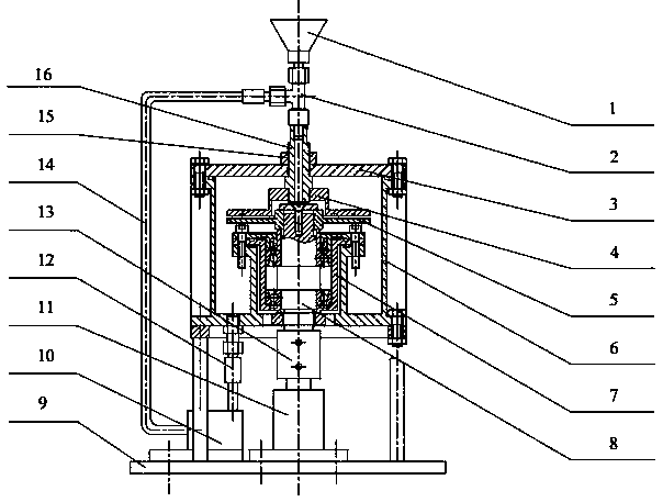
The invention discloses a continuous flow vertical planar liquid phase shearing device. The device comprises a base, a vertical motor is installed on the base, the vertical motor is connected to a lower shaft in a liquid chamber through a coupler, the lower shaft is connected to a lower disc, an upper disc in the liquid chamber is arranged above the lower disc, the upper disc is connected to an upper shaft provided with a material path, the upper shaft passes through the liquid chamber and is connected to one end of a t-branch pipe joint, other two ends of a t-branch pipe are respectively connected to a feeding inlet and a material returning pipe, the material returning pipe is connected to a hydraulic pump, the hydraulic pump is connected to the liquid chamber through the pipe joint, the liquid chamber comprises a chamber body, the upper end of the chamber body is provided with an upper cover plate and the lower end of the chamber body is connected to a stand column fixed to the base. The device has a reasonable structure and good working performances.
Description
technical field The invention relates to a liquid phase shearing device. Background technique Since the new century, graphene (Graphene) and molybdenum disulfide (MoS 2 ) has been a research hotspot all over the world, and their unique physical properties have been discovered one after another, such as the ultrafast electron transport and heat transport capabilities of graphene, single-layer or few-layer MoS 2 The optical response and radiation resistance properties caused by the unique energy level structure, etc., as far as the laboratory level is concerned, various new materials based on them have shown potential advantages in the fields of catalysis, energy and sensors, and have become the world's The key direction of each country's competing development. However, as far as the preparation of two-dimensional materials is concerned, their preparation has also gone through a relatively complicated process. Starting from the initial micromechanical exfoliation method, ion...
Claims
Login to View More Application Information
Patent Timeline
 Patent Type & AuthorityPatents(China)
IPC IPC(8): C01B32/19C01G39/06
Inventor莫亚梅张兴国袁国秋姚理荣曹敏
OwnerNANTONG UNIVERSITY