A rotary magnetic fluid generator

A magnetic fluid generator, rotary technology, applied in electromechanical devices, electrical components, etc., to reduce manufacturing costs, improve power coefficient and overall efficiency, and inhibit flow separation

Active Publication Date: 2019-03-01
XI AN JIAOTONG UNIV
View PDF12 Cites 1 Cited by
  • Summary
  • Abstract
  • Description
  • Claims
  • Application Information

AI Technical Summary

Problems solved by technology

If a traditional high-speed rotating generator is used to achieve electromechanical conversion, it is necessary to use a gearbox or an air compression turbine to achieve impedance matching, which brings about the above-mentioned problems of traditional devices

Method used


Image

  • A rotary magnetic fluid generator
  • A rotary magnetic fluid generator
  • A rotary magnetic fluid generator

Examples


Embodiment Construction

[0024] The present invention will be further described in detail below in conjunction with the accompanying drawings.

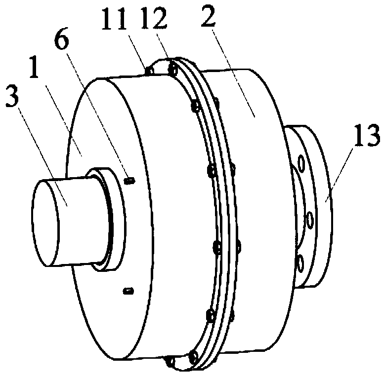
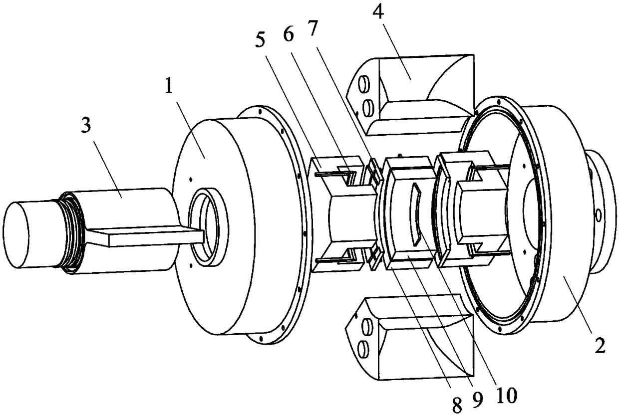
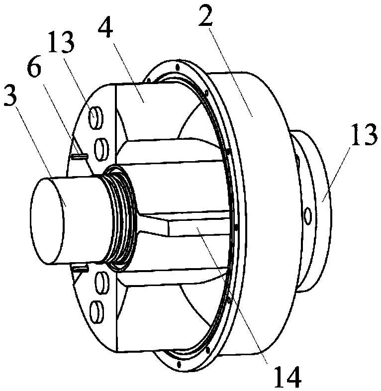
[0025] The appearance diagram and exploded view of the magnetic fluid generator provided by the present invention are shown in figure 1 and figure 2 , the technical scheme adopted is as follows:

[0026] The sealed cylinder is formed by connecting bolts 11 and nuts 12 at the flanges of the first half cylinder 1 and the second half cylinder 2 . The rotating shaft 3 is inserted before the sealing cylinder head cylinder, and the rotating shaft 3 can rotate back and forth in the sealing cylinder. The flanges of the first half cylinder 1 and the second half cylinder 2 and the journal of the rotating shaft 3 are all provided with sealing grooves for sealing the liquid metal in the cylinders. The first half-cylinder 1 and the second half-cylinder 2 are also provided with sealing holes for leading out the collector electrodes 6 . When the end 13 of the second ha...


PUM


Abstract

The invention discloses a rotary magnetohydrodynamic generator which comprises a sealing cylinder, and a rotary shaft provided with a piston, wherein the rotary shaft can make reciprocating torsion in the sealing cylinder; a convergent-divergent flow channel and conductive liquid metal are sealed in the sealing cylinder; rotation of the rotary shaft drives the liquid metal to flow back and forth in the convergent-divergent flow channel; a long and narrow arc gap is arranged at the narrowest part of the convergent-divergent flow channel; permanent magnets are arranged on the two sides of the arc gap; the two permanent magnets can generate high-intensity magnetic fields in directions perpendicular to the arc gap; the two permanent magnets are connected by U-shaped yokes to form a closed magnetic circuit; and current collection electrodes are arranged at the end part of the arc gap, and used for collecting current generated in a narrow channel and outwards outputting electric energy. The generator is suitable for a reciprocating driving force with a large force moment and a low speed, and has the characteristics of compact structure and high expansibility.

Description

technical field [0001] The invention relates to a power generating device, in particular to a rotary magnetic fluid generator. Background technique [0002] Wave energy is the energy generated by the movement of waves on the ocean surface. Wave energy can be used for different purposes, such as power generation, seawater desalination or as backup power for ships. Wave energy is the most unstable and irregular energy in ocean energy. The potential energy difference formed by wave motion can be transformed into other more regular energy outputs. According to statistics, the average density of offshore wind energy in the world is 0.5kW / m 2 , while the average density of wave energy is 2-3kW / m 2 . The wave energy hitting the coastline in the world is on the order of 1TW, and if considering the wave energy in open seas, the wave energy is on the order of 10TW (equivalent to the current energy consumption in the world). The conversion of energy in a common wave energy power g...

Claims


Application Information

Patent Timeline
Patent Type & Authority Patents(China)
IPC IPC(8): H02K44/08H02K44/10
CPCH02K44/085H02K44/10
Inventor 谢永慧姜伟张荻
Owner XI AN JIAOTONG UNIV
Why Eureka
Try Eureka