Non-core follow-up self-sundry-cleaning farmland residual film collecting roller and mulching film recovery machine composed of roller
A technology of residual film picking and operation machine, which is applied in the field of agricultural machinery, can solve problems such as difficulties in recycling operations, achieve the effect of improving operation efficiency, reducing sundries, and ensuring normal operation
- Summary
- Abstract
- Description
- Claims
- Application Information
AI Technical Summary
Problems solved by technology
Method used
Image
Examples
Embodiment 1
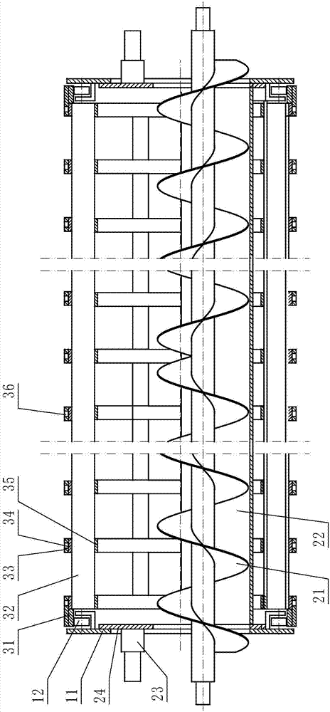
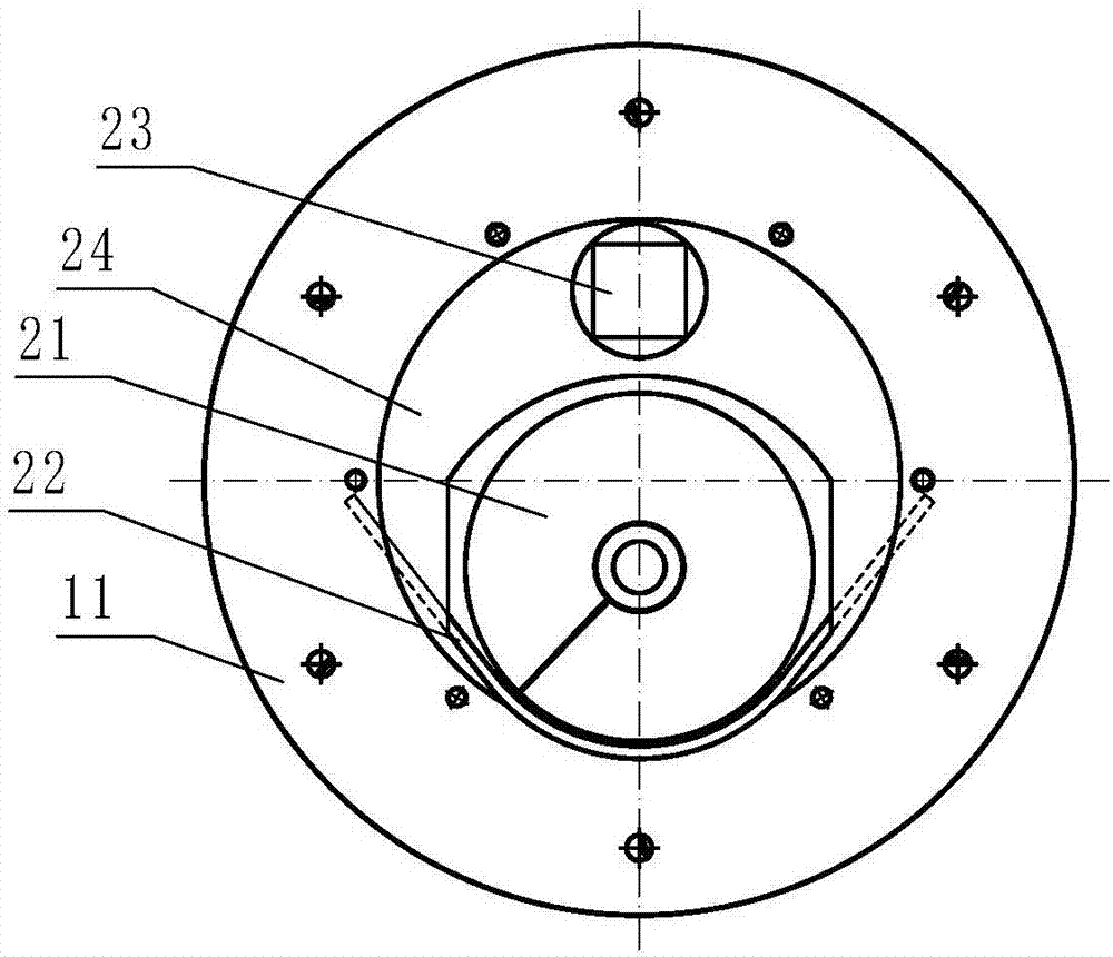
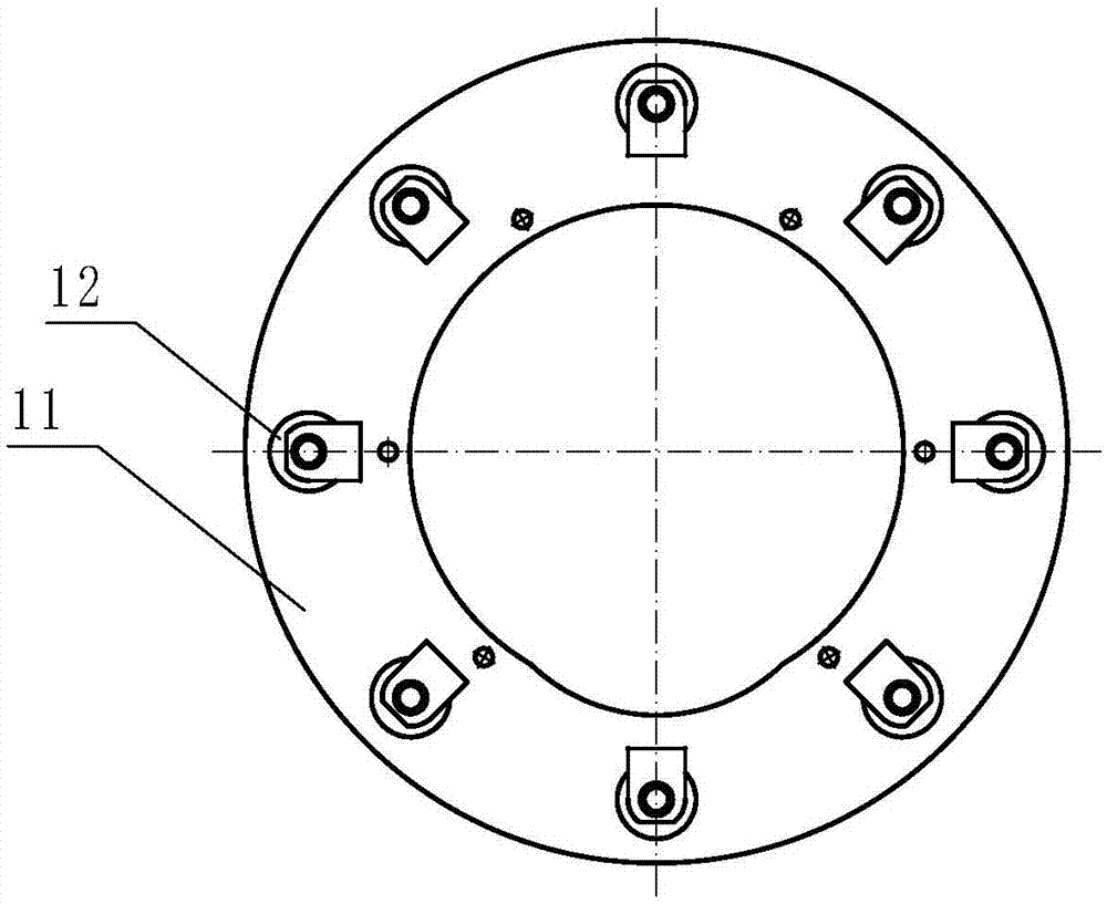
[0033] Embodiment 1: refer to Figure 1-5 , is a structural schematic diagram of Embodiment 1 of the present invention, comprising two opposite fixed plates A11 and a drum body 34 between the two fixed boards A11, the drum body 34 is a structure composed of warp strips and weft strips A hollow frame in the shape of a squirrel cage.
[0034] Between the fixed plate A11 and the roller body 34, a roller group 12 and an annular track-shaped body 31 are arranged. The roller group 12 is arranged on the fixed plate A11. Circumferential lines are arranged on the fixed plate A11, the ring-shaped track-shaped body 31 is arranged on the two ends of the roller body 34, and the roller set 12 is positioned at the inner edge of the ring-shaped track-shaped body 31, so that the roller body 34 can Rotate on roller group 12.
[0035] One week of the inner wall of the drum body 34 is provided with a miscellaneous groove 32, the miscellaneous groove 32 is an axial groove-shaped body, and the op...
Embodiment 2
[0038] Embodiment 2: refer to Figure 6 , is a structural schematic diagram of Embodiment 2 of the present invention. Compared with Embodiment 1, the difference of this embodiment is that the ring-shaped groove 37 and concave groove are simultaneously provided on the strip-shaped annular body of the film-picking tooth chain plate track 33 Hole 36.
Embodiment 3
[0039] Embodiment 3: refer to Figure 7 , is a structural schematic diagram of Embodiment 3 of the present invention. Compared with Embodiments 1 and 2, the difference of this embodiment is that: the roller set 12 is arranged at both ends of the roller body 34, and the ring-shaped track-shaped body 31 is arranged on On the two fixing plates A11 , the roller set 12 is located on the inner edge or the outer edge of the annular track-shaped body 31 , so that the roller body 34 can rotate on the roller set 12 .
PUM
 Abstract
Description
Claims
Application Information
 - R&D
- Intellectual Property
- Life Sciences
- Materials
- Tech Scout
- Unparalleled Data Quality
- Higher Quality Content
- 60% Fewer Hallucinations
Browse by: Latest US Patents, China's latest patents, Technical Efficacy Thesaurus, Application Domain, Technology Topic, Popular Technical Reports.
© 2025 PatSnap. All rights reserved.Legal|Privacy policy|Modern Slavery Act Transparency Statement|Sitemap|About US| Contact US: help@patsnap.com


