Draw bench knife roll

A technology of rod pulling machine and knife roller, which is applied in the direction of harvesters, agricultural machinery and implements, etc., can solve problems such as leakage of rods, heavy stress on the tool, and easy damage to the tool, so as to improve the service life and reduce the Small vibration and impact, reducing wear effect

Inactive Publication Date: 2017-11-24
GUIZHOU UNIV
View PDF3 Cites 1 Cited by
  • Summary
  • Abstract
  • Description
  • Claims
  • Application Information

AI Technical Summary

Problems solved by technology

[0004] The object of the present invention is to provide a cutter roll of a rod pulling machine to solve the problems that the existing

Method used


Image

  • Draw bench knife roll
  • Draw bench knife roll

Examples


Embodiment Construction

[0013] In order to make the purpose, technical solution and advantages of the present invention clearer, the invention will be further described in detail with the accompanying drawings.

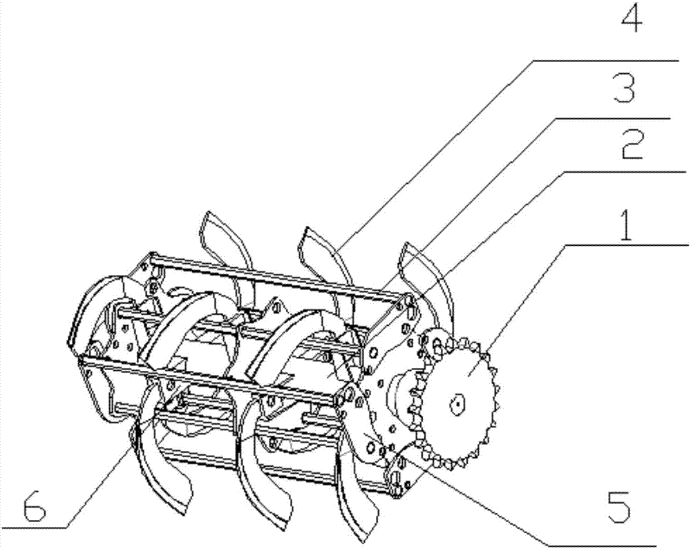
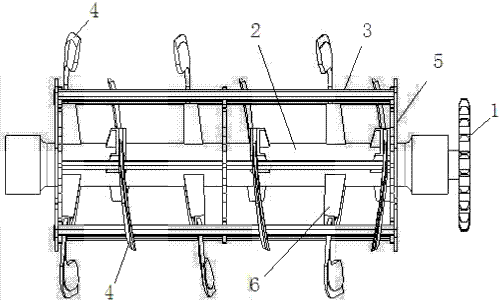
[0014] Refer to attached figure 1 with figure 2 , the present embodiment provides a bar pulling machine knife roller, including a knife roller driving sprocket 1, a knife roller shaft 2, a cross bar 3 and a rotary tiller machete 4, and the knife roller driving sprocket 1 is installed and fixed on the knife roller shaft 2 One end is used for transmission link with the driving device. The cross bar 3 is a hexagonal square steel rod used to overwhelm the tobacco stalk. Parallel to each other, multiple groups of installation panels 5 are fixedly arranged on the cutter roller shaft 2 along the length direction, and the two ends of the cross bar 3 are respectively fixed on the outermost installation panels 5 at both ends of the cutter roller shaft 2, and the cutter roller shaft The outer side o...


PUM


Abstract

The invention provides a draw bench knife roll. The knife roll comprises a knife roll driving chain wheel, a knife roll shaft, cross bars and rotary tillage curved knives, the knife roll driving chain wheel is fixedly mounted at one end of the knife roll shaft and used for being connected with a driving device in a transmission mode, and the cross bars are distributed on the outer side of the knife roll shaft in the peripheral direction and are parallel to the knife roll shaft; a mounting embedded plate is vertically fixed to the knife roll shaft, the cross bars are all fixed to the mounting embedded plate, and multiple sets of rotary tillage curved knives are distributed on the outer side of the knife roll shaft in the length direction; each set of rotary tillage curved knives comprises two rotary tillage curved knives totally, the two rotary tillage curved knives of each set are distributed at an angle of 180 degrees, and the rotary tillage curved knives of two adjacent sets of the rotary tillage curved knives are arranged at an angle of 90 degrees in a staggered mode; the knife edge ends of the rotary tillage curved knives all extend out to the outer sides of the cross bars, and the rotary tillage curved knives are fixed to the mounting embedded plate through tool mounting supports. The draw bench knife roll solves the problems that a draw bench manufactured in the existing knife roll mounting mode has loopholes, and the tool is large in bearing stress and easy to damage. The invention belongs to the field of agricultural tobacco machines.

Description

technical field [0001] The invention relates to a stalk pulling knife roller, which belongs to the field of agricultural tobacco machinery. Background technique [0002] Tobacco stalk is the largest by-product in tobacco production, with an annual output of about 4.5 million tons. Tobacco stalk is a by-product of a special economic crop. Because it contains nicotine and carries tobacco bacteria, it is neither suitable for feed nor It cannot be directly returned to the field, so the tobacco rods are generally pulled out by a rod pulling machine and crushed to be used as raw materials for biomass energy or polymeric materials. Since the tobacco rod has high mechanical properties such as compression resistance, shear strength, and bending strength, it needs a higher strength and better mechanical properties in the process of pulling out the rod, and a reasonable adjustment should be taken for the cutter of the cutter roll. Location layout and reasonable installation method. ...

Claims


Application Information

Patent Timeline
IPC IPC(8): A01D45/16
Inventor 张大斌舒成松张纪利余朝静覃荣韦建玉吴峰李俊霖
Owner GUIZHOU UNIV
Why Eureka
Try Eureka