
Permanent magnet installation tool and method of electromagnetic actuator mover

An electromagnetic actuator and installation method technology, which is applied in metal processing, manufacturing tools, metal processing equipment, etc., can solve the problems of difficulty in ensuring the accuracy of the installation position of permanent magnets and difficulties in the installation process, and achieve improved operability and safety High performance, easy operation, and the effect of ensuring the accuracy of the relative position

Active Publication Date: 2020-01-14
武汉源海博创科技有限公司
View PDF8 Cites 0 Cited by
  • Summary
  • Abstract
  • Description
  • Claims
  • Application Information

AI Technical Summary

Problems solved by technology

[0005] In view of the above defects or improvement needs of the prior art, the present invention provides a permanent magnet installation tool and method for the mover of an electromagnetic actuator with simple structure, convenient operation, time-saving and labor-saving, and solves the problem of multiple permanent magnets in the prior art. When the magnets are spliced ​​side by side, the adjacent permanent magnets will repel each other, the installation process is very difficult, and it is difficult to guarantee the accuracy of the installation position of the permanent magnets.

Method used


Image

  • Permanent magnet installation tool and method of electromagnetic actuator mover
  • Permanent magnet installation tool and method of electromagnetic actuator mover
  • Permanent magnet installation tool and method of electromagnetic actuator mover

Examples


Embodiment Construction

[0030] In order to make the object, technical solution and advantages of the present invention clearer, the present invention will be further described in detail below in conjunction with the accompanying drawings and embodiments. It should be understood that the specific embodiments described here are only used to explain the present invention, not to limit the present invention. In addition, the technical features involved in the various embodiments of the present invention described below can be combined with each other as long as they do not constitute a conflict with each other.

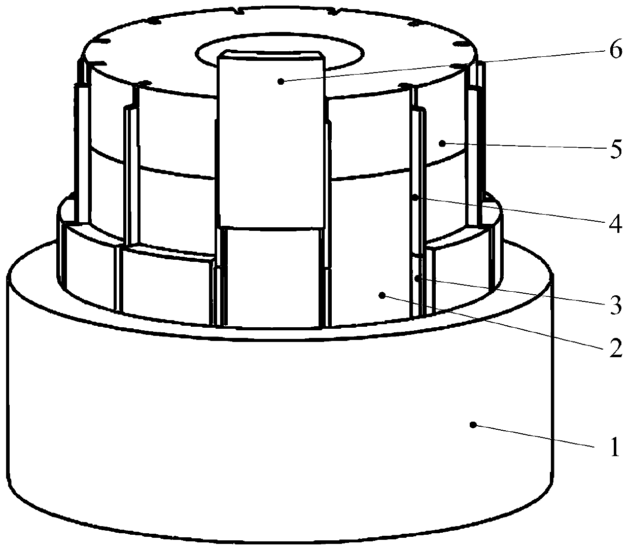
[0031] figure 1 It is a three-dimensional structural schematic diagram of a permanent magnet installation tool for an electromagnetic actuator mover according to an embodiment of the present invention. Such as figure 1 As shown, a permanent magnet installation tool for an electromagnetic actuator mover disclosed by the present invention includes: an outer limit sleeve 1 made of aluminum alloy,...


PUM


Abstract

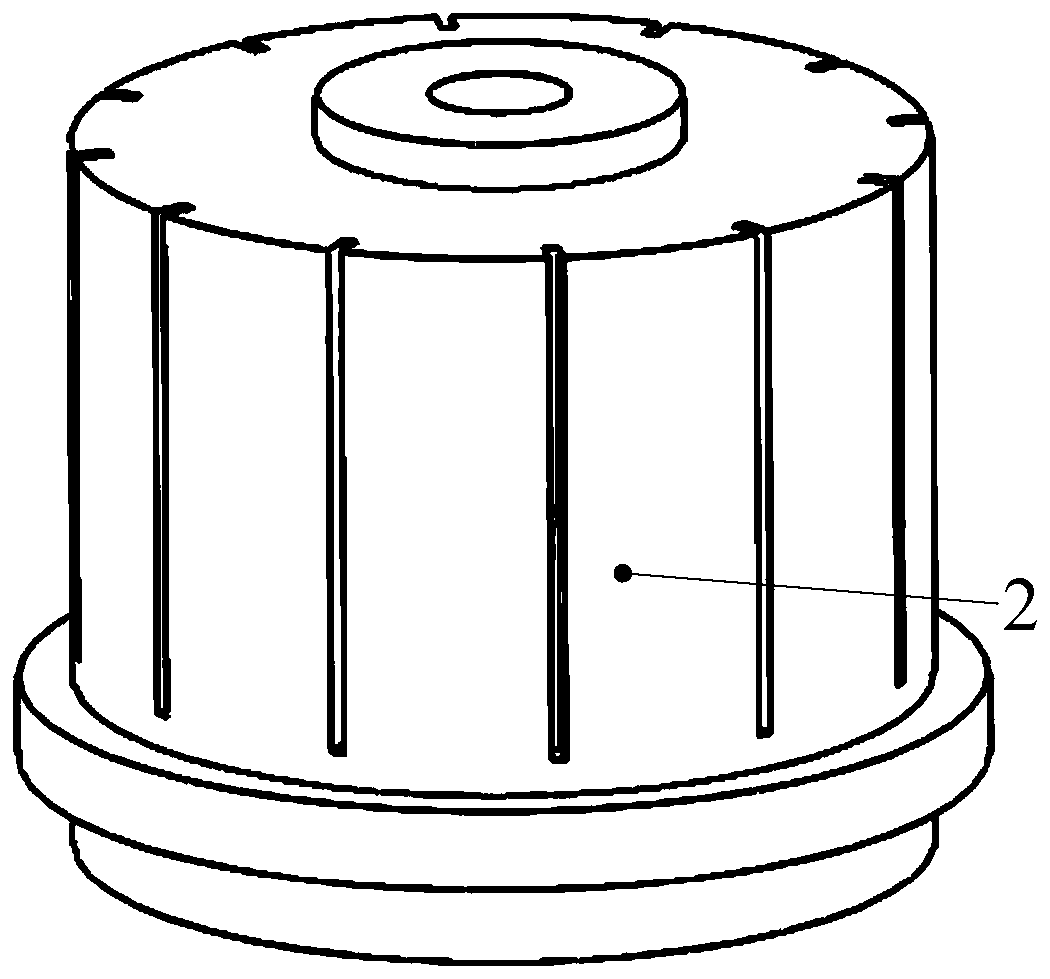
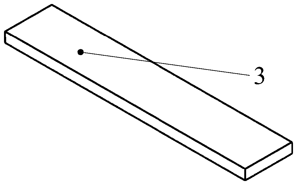
The invention discloses a permanent magnet installation tool of an electromagnetic actuator rotor. The permanent magnet installation tool of the electromagnetic actuator rotor comprises an outside limiting sleeve (1), an actuator rotor framework (2), a lower clapboard (3), an upper clapboard (4) and an installation assistant sleeve (5). The outside limiting sleeve (1) sleeves outside the actuator rotor framework (2); the outside limiting sleeve (1) and the actuator rotor framework (2) are placed on the same plane; and the installation assistant sleeve (5) is installed above the actuator rotor framework (2). The invention further discloses a permanent magnet installation method of the electromagnetic actuator rotor. According to the installation tool provided by the invention, a permanent magnet is limited through the lower clapboard and the outside limiting sleeve, so that the problem that the permanent magnets installed onto the actuator rotor framework are offset due to a repelling force between each two adjacent magnets can be solved, other permanent magnets can be installed conveniently, and the problem that the last one or two permanent magnets cannot be installed due to uneven clearance and mutual repulsion is solved.

Description

technical field [0001] The invention relates to the technical field of electromagnetic actuators, in particular to a permanent magnet installation tool and method for an electromagnetic actuator mover. Background technique [0002] Due to the high reliability of passive vibration isolators, passive control is usually used to isolate the vibration source. However, with the continuous development of science and technology, the vibration requirements for the environment and equipment are getting higher and higher, and passive vibration isolation can no longer fully meet people's needs. Therefore, active control of structural vibration through active components has attracted more and more attention. [0003] Actuator is an important device for active vibration control. Its function is to control the vibration response of the system by applying control force to the control object according to the determined control law. Electromagnetic actuators are suitable for occasions with l...

Claims


Application Information

Patent Timeline
Patent Type & Authority Patents(China)
IPC IPC(8): B23P19/04B25B11/02
CPCB23P19/04B25B11/02
Inventor 陈凡周超闫政涛
Owner 武汉源海博创科技有限公司
Learn More