
Motorcycle throttle body machining fixture

A throttle body and motorcycle technology, applied in the direction of manufacturing tools, metal processing equipment, metal processing machinery parts, etc., can solve the problems of low equipment utilization rate, long processing cycle, waste products, etc., to improve the utilization rate of machine tools, improve Parts qualified rate, the effect of shortening the process flow

Pending Publication Date: 2017-11-24
SICHUAN HONGGUANG AUTO MACHINERY ELECTRONICS
View PDF10 Cites 5 Cited by
  • Summary
  • Abstract
  • Description
  • Claims
  • Application Information

AI Technical Summary

Problems solved by technology

The existing fixture adopts the independent replacement design of a single fixture. The fixture needs to be replaced and debugged every time the model is changed. Therefore, the changeover time usually takes 1-1.5 days, the production efficiency is low, and the equipment utilization rate is not high.
The existing fixture adds a process reference to the product, so that the processing flow has two more processes: 1. Machining two process reference positioning holes and milling process reference surface; 2. Removing the process reference (when all processes are completed), making the processing cycle longer , low production efficiency
The existing fixture uses one oil cylinder to press two points, and the pressing force is insufficient, which leads to unstable processing quality of the parts; and the pressing point is at the main channel hole, which is deformed due to the pressing force, making the roundness of the main channel hole exceeding Difference
The existing fixtures do not have parts clamping error prevention devices and devices that provide quick clamping. There are potential threats of clamping errors or improper clamping during processing, resulting in waste products due to incorrect clamping or improper clamping.

Method used


Image

  • Motorcycle throttle body machining fixture
  • Motorcycle throttle body machining fixture
  • Motorcycle throttle body machining fixture

Examples


Embodiment Construction

[0020] The present invention will be further described below in conjunction with accompanying drawing, protection scope of the present invention is not limited to the following:

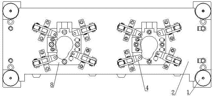
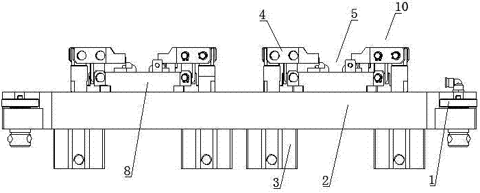
[0021] Such as Figure 1~Figure 4 As shown, a motorcycle throttle body processing fixture includes a ball joint locking and positioning mechanism 1, a bridge plate 2, a clamp positioning unit 5 and a pressing unit 10, and the two ends of the bridge plate 2 pass through the ball joint locking and positioning mechanism 1 They are respectively connected to the tailstock on the machine tool and the L plate of the indexing head, and the bridge plate 2 is provided with two fixture positioning units 5 and multiple pressing units 10;

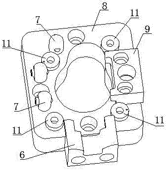
[0022] Specifically, the clamp positioning unit 5 includes a clamp base 8, a positioning block A6, a moving steel ball screw assembly 7 and a positioning block B9, the clamp base 8 is fixed on the bridge plate 2 by screws, and the bridge plate 2 and the clamp base 8 There is ...


PUM


Abstract

The invention discloses a motorcycle throttle body machining fixture. The motorcycle throttle body machining fixture comprises bulb locking and positioning mechanisms, a bridge plate, two fixture positioning units and a plurality of pressing units. Two ends of the bridge plate are connected with a tailstock of a machine tool and an L plate of an index head through the bulb locking and positioning mechanisms respectively, and the two fixture positioning units and the multiple pressing units are arranged on the bridge plate. Each fixture positioning unit comprises a fixture base, a positioning block A, a plurality of moving steel ball screw components and a positioning block B, wherein the fixture base is fixed to the bridge plate, the bridge plate and the fixture base are provided with gourd-shaped holes matched with motorcycle throttle bodies, the positioning block A, the positioning block B and positioning bosses are arranged at the edge of the gourd-shaped hole of the fixture base, each positioning boss of the fixture base corresponds to one pressing unit, and the moving steel ball screw components with pre-tightening and false-proof functions are arranged on the fixture base. The motorcycle throttle body machining fixture has advantages of accuracy in positioning, simplicity in operation, high production efficiency and high machining quality.

Description

technical field [0001] The invention relates to the technical field of mechanical processing, in particular to a motorcycle throttle body processing fixture. Background technique [0002] In the mechanical processing and manufacturing industry, especially in the processing of auto parts, there are often many varieties of small batch production. The existing fixture adopts the independent replacement design of a single fixture. The fixture needs to be replaced and debugged every time the model is changed. Therefore, the changeover time usually takes 1-1.5 days, the production efficiency is low, and the equipment utilization rate is not high. The existing fixture adds a process reference to the product, so that the processing flow has two more processes: 1. Machining two process reference positioning holes and milling process reference surface; 2. Removing the process reference (when all processes are completed), making the processing cycle longer , Low production efficiency....

Claims


Application Information

Patent Timeline
IPC IPC(8): B23Q3/08
CPCB23Q3/08B23Q2703/04
Inventor 张兴华刘晓翠王国荣刘军秦峰卢莜莜傅艳
Owner SICHUAN HONGGUANG AUTO MACHINERY ELECTRONICS
Learn More