Micro lifting machine

A technology of lifts and lifting devices, applied in the field of lifts, can solve the problems of simple structure, low safety factor, waste of energy, etc., and achieve the effects of saving space, increasing service life and safety factor, and reducing support force

Inactive Publication Date: 2017-11-24
TAIZHOU AIRUISIKE MOLD CO LTD
View PDF0 Cites 0 Cited by
  • Summary
  • Abstract
  • Description
  • Claims
  • Application Information

AI Technical Summary

Problems solved by technology

[0002] The lift is a machine used for equipment lifting, generally used for equipment repair and maintenance, through lifting the equipment to achieve the purpose of comprehensive inspection and maintenance of the bottom and side of the equipment, most lifts Using a single lifting force is a waste of energy, and the level of the platform needs to be manually monitored and adjusted. A single lifting force can easily cause uneven force on the loading platform and cause the platform to tilt. The safety factor is low, the humanized design is not in place, and the lifting speed of the equipment is high. Only set the upper limit of speed, no intelligent control speed equipment, simple structure, single function

Method used


Image

  • Micro lifting machine

Examples


Embodiment Construction

[0012] The following will clearly and completely describe the technical solutions in the embodiments of the present invention with reference to the accompanying drawings in the embodiments of the present invention. Obviously, the described embodiments are only some of the embodiments of the present invention, not all of them. Based on the embodiments of the present invention, all other embodiments obtained by persons of ordinary skill in the art without making creative efforts belong to the protection scope of the present invention.

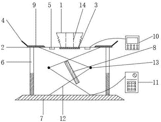
[0013] see figure 1 , the present invention provides a technical solution: a new type of micro-lift, including a lifting support platform 1, a main lifting platform 2, an external level 3, a safety grip 4, a speed display 5, a vertical

[0014] Straight lifting device 6, horizontal base plate 7, hydraulic device 8, soft landing protection pad 9, intelligent controller 10, hydraulic regulator 11, scissor support 12, bearing column 13, auxiliary li...


PUM


Abstract

The invention discloses a micro-lift, which comprises a lifting support platform, a main lifting platform, an external level, a safety grip, a speed display, a vertical lifting device, a horizontal bottom plate, a hydraulic pressure device, a soft landing protection pad, Intelligent controller, hydraulic regulator, scissor bracket, bearing column, auxiliary lifting device, the main lifting platform is set on the lower side of the lifting platform, and an external level is set on the main lifting platform. Both sides of the main lifting platform are equipped with safety grabs, and a speed indicator is installed on the lower side. Vertical lifting devices are arranged on both sides of the speed indicator, and a horizontal base plate is installed on the lower side of the vertical lifting device. This new type of micro-lift uses multiple lifting forces to act on the lifting platform at the same time to ensure that when the volume of the lift is small, it can maintain a large lifting load, and at the same time increase the safety, stability and intelligence of the scissor structure and the overall equipment. , Improve speed control, safe and reliable.

Description

technical field [0001] The invention relates to the technical field of lifts, in particular to a micro lift. Background technique [0002] The lift is a machine used for equipment lifting, generally used for equipment repair and maintenance, through lifting the equipment to achieve the purpose of comprehensive inspection and maintenance of the bottom and side of the equipment, most lifts Using a single lifting force is a waste of energy, and the level of the platform needs to be manually monitored and adjusted. A single lifting force can easily cause uneven force on the loading platform and cause the platform to tilt. The safety factor is low, the humanized design is not in place, and the lifting speed of the equipment is high. Only the upper limit of speed is set, without intelligent speed control equipment, simple structure and single function. Contents of the invention [0003] The purpose of the present invention is to provide a novel micro-lift to solve the problems ...

Claims


Application Information

Patent Timeline
IPC IPC(8): B66F7/08B66F7/28
CPCB66F7/0666B66F7/28
Inventor 王晶
Owner TAIZHOU AIRUISIKE MOLD CO LTD
Why Eureka
Try Eureka