
Wooden shock-isolation device

A kind of shock-isolation and wooden technology, which is applied in the direction of earthquake resistance, building components, building types, etc., can solve the problems of excessive vertical bearing capacity and vertical stiffness, increase economic cost, and aggravate the earthquake damage of wooden structures, so as to achieve installation and Easy and convenient to replace, reduce earthquake damage and increase project cost

Active Publication Date: 2017-11-24
WUHAN UNIV OF TECH
View PDF13 Cites 1 Cited by
  • Summary
  • Abstract
  • Description
  • Claims
  • Application Information

AI Technical Summary

Problems solved by technology

Traditional energy-dissipating dampers, such as rubber shock-absorbing pads, have excessive vertical bearing capacity and vertical stiffness, and are connected to the bottom of the ground beam by bolts during installation. The structure formed with concrete is soft at the top and rigid at the bottom. The concrete itself has a relatively high rigidity, and a rubber shock-isolating pad with strong rigidity is used. The rubber shock-isolating pad has an obvious amplification effect on the seismic response of the wooden structure, which is bound to increase the vibration of the wooden structure. Harmful, increase the economic cost; and the ground beam plate should not open multiple bolt holes, rubber shock absorber is not suitable for installation in the transition layer of wood structure or wood-concrete structure, and it is not harmonious with the environmental protection and affinity of wood, which has the advantages of Strong sense of violation

Method used


Image

  • Wooden shock-isolation device
  • Wooden shock-isolation device
  • Wooden shock-isolation device

Examples


Embodiment Construction

[0034] The present invention will be further described in detail below in conjunction with the accompanying drawings and specific embodiments to facilitate a clear understanding of the present invention, but they do not limit the present invention.

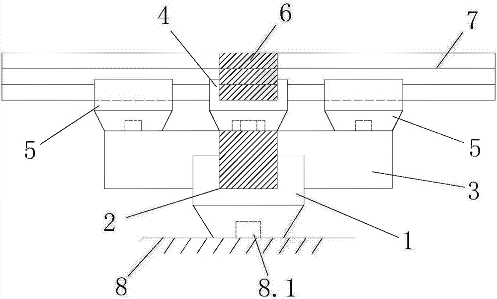
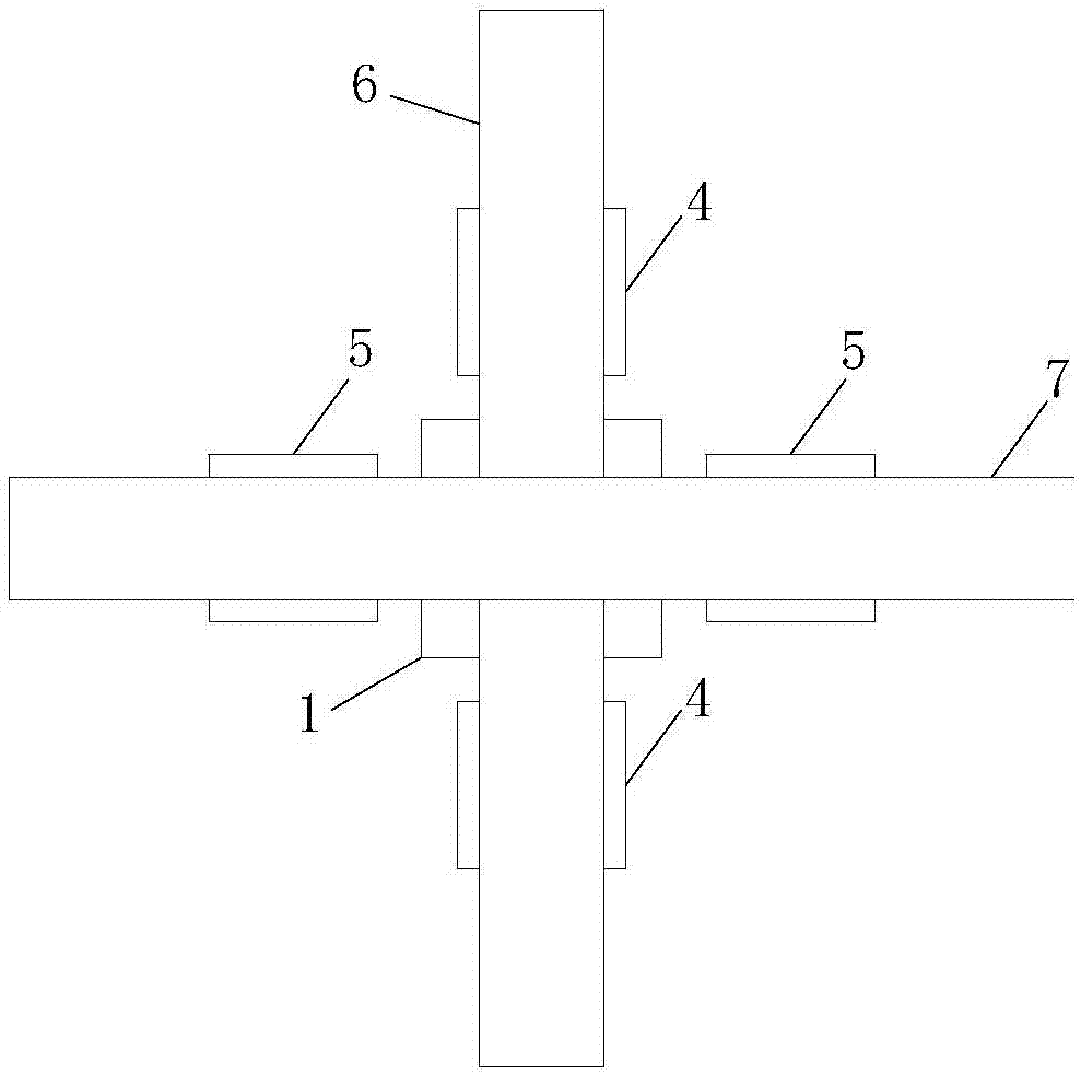
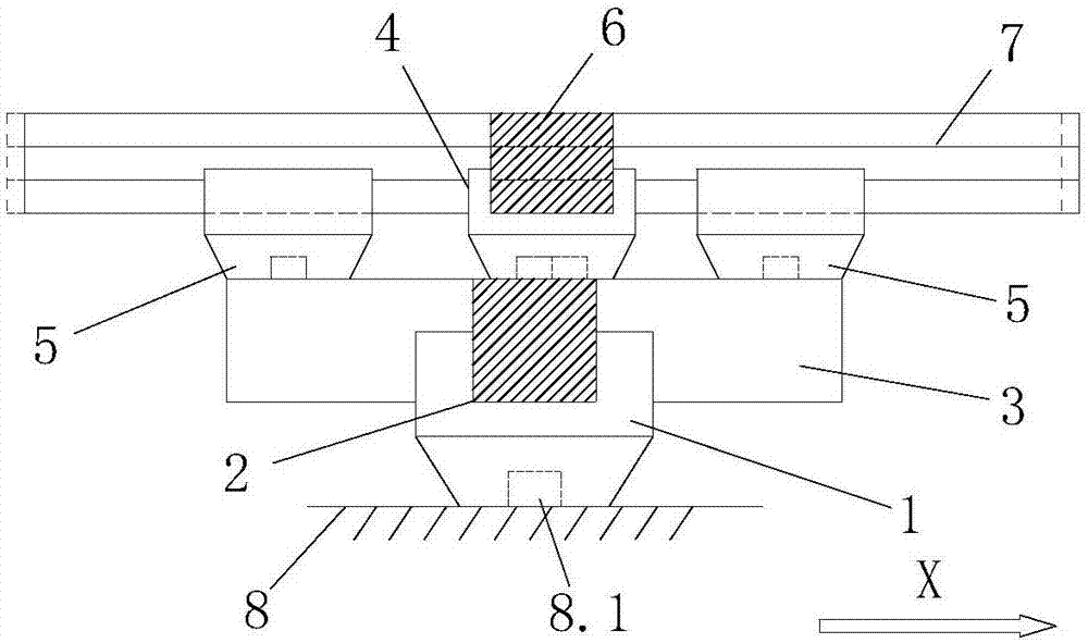
[0035] like Figure 1-17 As shown, the present invention includes a bucket 1, a mudway arch 2 and a Chinese arch 3, and the center of the bottom of the bucket 1 is provided with a square notch 1.1 for connecting the base 8, and the notch 1.1 can be connected with the base 8 (that is, concrete The third mortise 8.1 reserved on the top surface of the frame beam or column) forms a mortise and tenon connection, and the top of the bucket 1 is provided with a first installation groove 1.2 and a second installation groove 1.3 arranged in a cross shape, and the mudway arch 2 is installed In the first installation groove 1.2, the Huagong 3 is buckled on the mudway arch 2 to match the second installation groove 1.3, and the top of the mudwa...


PUM


Abstract

The invention discloses a wooden shock-isolation device. The wooden shock isolation device comprises a cap block, an axial bracket arm and a flower arm, wherein a notch is formed in the bottom of the cap block, a first installing groove and a second installing groove are formed in the top of the cap block, the axial bracket arm is installed in the first installing groove, and the flower arm is buckled on the axial bracket arm and matched with the second installing groove; first small blocks are installed at the two ends of the top of the axial bracket arm correspondingly, a first strip-shaped groove is formed in the top parts of the first small blocks in a penetrating mode, and the first small blocks can move on the top of the axial bracket arm in the direction perpendicular to the first trip-shaped groove in a limited range; second small blocks are installed at the two ends of the top of the flower arm, second strip-shaped grooves are formed in the top parts of the second small blocks, and the second small blocks can move on the top of the flower arm in the direction perpendicular to the second strip-shaped groove in the limited range; the penetrating direction of the first strip-shaped groove is perpendicular to the penetrating direction of the second strip-shaped groove. The wooden shock-isolation device is simple in structure, low in economic cost, stable and reliable in performance, and the fact that the wooden shock-isolation device which is installed in a transition layer of a wood-concrete hybrid structure is helpful for improving the seismic capacity of the structure.

Description

technical field [0001] The invention belongs to the technical field of structural vibration energy consumption and shock absorption, and in particular relates to a wooden shock isolation device, which consumes multiple energy by relying on nonlinear deformation of materials, rigid body rotation of components and frictional slip between contact surfaces of various components. Background technique [0002] In order to improve the anti-seismic capacity of wood-concrete hybrid structures and reduce the earthquake damage of pure wood structures in strong earthquake areas, installing energy-dissipating dampers in the structures is one of the effective measures. Traditional energy-dissipating dampers, such as rubber shock-absorbing pads, have excessive vertical bearing capacity and vertical stiffness, and are connected to the bottom of the ground beam by bolts during installation. The structure formed with concrete is soft at the top and rigid at the bottom. The concrete itself has...

Claims


Application Information

Patent Timeline
IPC IPC(8): E04B1/98E04H9/02
CPCE04H9/021E04H9/023
Inventor 王雪亮谭柱王小丽魏凯睿彭磊欧阳清容
Owner WUHAN UNIV OF TECH
Learn More