Exhaust valve with dual control chambers and dual floating bodies

A dual control and exhaust valve technology, applied in the direction of control valves, valve details, valve devices, etc., can solve problems such as short service life, large economic losses for users, and air can not be discharged, so as to achieve the effect of improving service life and reasonable design

Active Publication Date: 2017-11-24
QUANZHOU YUANLUN AUTOMATIC CONTROL VALVE TECH CO LTD
View PDF9 Cites 11 Cited by
  • Summary
  • Abstract
  • Description
  • Claims
  • Application Information

AI Technical Summary

Problems solved by technology

In the hot water heating system, there is often air in the embassy due to the evaporation and cooling of water. Since the system is usually closed, the air cannot be discharged from the piping system, causing air plugs, which affect the heat dissipation and circulation of the heating system. Usually, it is used in the piping system. Set an exhaust valve at the top of the valve to solve the problem. Chinese Patent No. 87209560 announced an automatic sensitive exhaust valve. A vacuum floating ball is set in the valve body. The floating ball is a glass floating ball. The air hole is opened and closed by the bump on the top of the floating ball. Although the exhaust valve of this result can remove the air in the pipeline system, because the bump and the air outlet are often misaligned and the exhaust is not sensitive, it also causes water to overflow. Due to the many debris inside the pipeline, if the debris enters the valve body, it will block the exhaust port or hinder the movement of the floating ball. If the debris gets stuck in the seal, it will easily lead to exhaust and drainage, and the introduction of floods will waste a lot of water, thus affecting the drainage. The normal operation of the air valve also adopts single seal and single exhaust. When the exhaust valve enters water, the floating ball controls the sealing surface, but the pipeline is often impacted by water and will accumulate secondary air. At this time, the secondary air cannot be realized. Exhaust will cause the pipeline to break easily if the gas is not exhausted, and damage the water appliances, resulting in large economic losses for users and unsatisfactory use effects
[0004] At present, the Chinese patent number ZL 201220317289.6 has announced a double-port exhaust valve, which includes a valve body, a valve stem and a valve disc. The lower part of the valve body is provided with a valve port for gas and fluid to enter. There is a valve cover directly above the valve port, the valve disc can be opened and closed on the valve port, and the valve stem can be lifted up and down in the valve body, one end of which is fixedly connected with the valve disc, and the other end extends out of the valve cover Connected with the driving device, the left and right sides of the valve body are respectively provided with left and right exhaust chambers connected with the valve port, and the left and right exhaust chambers are respectively equipped with floating balls that can float up and down. The valve body is located above the left and right exhaust chambers and is also provided with an exhaust end cover respectively, and each exhaust end cover is respectively provided with an exhaust port, and the valve body is located between the exhaust end cover and the valve cover. The upper part is also equipped with a protective cover, and there is a gap for the gas to flow out between the protective cover and the two exhaust end covers. The valve body is located inside the circumference of the valve port and is provided with a filter. There is a filter on the inside, which can realize the filtering function. Since the filter fails to block the valve body, the filter is easy to fall off and fall into the pipeline, and finally cannot perform the filtering function, resulting in the filtering function not being durable and having a short service life. The design of the filter is unreasonable. This kind of phenomenon has already appeared in some parts of the market. Users often report that the scope of application of this prior art is limited and it can only be used on larger pipelines. It is not suitable for small pipelines and is a waste of cost. , and this patented technology can be installed and used in large or small pipelines, and it also adopts single seal and double exhaust. When the exhaust valve enters water, the floating ball controls the sealing surface, but the pipeline is often impacted by water and will produce If the secondary air is accumulated, the secondary exhaust cannot be realized at this time, which will cause the pipeline to be easily broken due to the exhaustion of the gas, and the water appliances will be damaged, which will also cause a large loss to the user's economy, and the use effect is also unsatisfactory. The above-mentioned In the prior art, no buffer spring is designed above the floating ball. When the water enters the floating ball, the impact force is relatively large, resulting in frequent damage to the floating ball, short service life, and loss of exhaust function. The exhaust valve must be replaced frequently. Can not bring good economic benefits to users

Method used


Image

  • Exhaust valve with dual control chambers and dual floating bodies
  • Exhaust valve with dual control chambers and dual floating bodies
  • Exhaust valve with dual control chambers and dual floating bodies

Examples


Embodiment Construction

[0029] The present invention will be further described in conjunction with the accompanying drawings and specific embodiments.

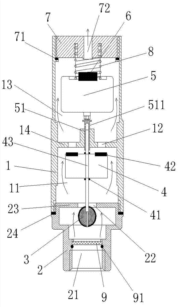
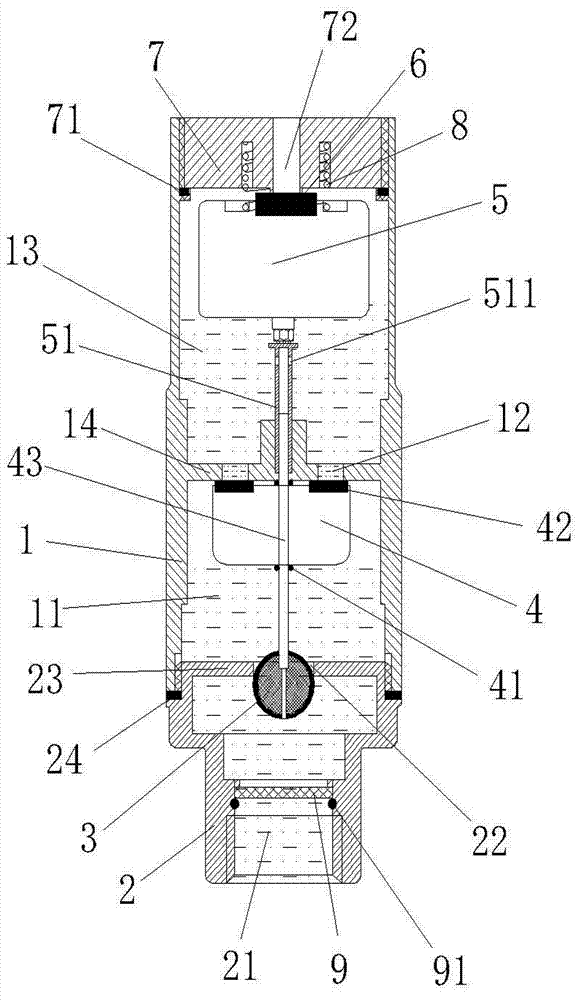
[0030] refer to Figure 1 to Figure 7 As shown, a double control room double floating body exhaust valve of the present invention includes a valve body 1, an upper valve cover 7, and a lower valve cover 2, and a longitudinal water inlet channel 21 is provided below the lower valve cover 2, and the A valve seat 23 and an exhaust port 22 are arranged above the lower valve cover 2, a sealing gasket 24 is also provided between the valve body 1 and the lower valve cover 2, and a valve seat 14 and an exhaust port are arranged inside the valve body 1. The air port 12, the upper valve cover 7 and the lower valve cover 2 are connected to the valve body 1 by threads, and the sealing floating body 3 is arranged at the exhaust port 22 of the valve seat 23 of the lower valve cover 2, and is connected with the telescopic floating rod. The upper floating rod 51 in...


PUM


Abstract

The invention relates to an exhaust valve, and provides an exhaust valve with dual control chambers and dual floating bodies. A sealing floating body is arranged at an exhaust port of a valve base of a lower valve cover and connected with a lower floating rod in a telescopic floating rod. An upper floating rod in the telescopic floating rod passes through an internal valve base of a valve body and is connected with the upper floating body. A locating slot is formed in the outer side of the lower side of the upper floating rod, and a locating pin matched with the locating slot is further arranged on the outer side of the lower floating rod. The lower floating body is arranged in the middle of the lower floating rod, sealing gaskets are arranged on the lower floating body, and a sealing gasket and spring bases are also arranged on the upper floating body. Groove spring bases are arranged on the lower side of an upper valve cover, an exhaust hole is further formed in the middle of the upper valve cover, and buffer springs are arranged between the spring bases of the upper floating body and the groove spring bases of the upper valve cover. A filter screen is further arranged at a water inlet end of the lower valve cover and is fixed with fixing clamp rings. Debris can be prevented from entering into the valve body, the safety of a water delivery pipeline can be guaranteed, and the exhaust valve with dual control chambers and dual floating bodies is good in sealing property, simple in structure, convenient to maintain and long in service life and also has a filtering function.

Description

technical field [0001] The invention relates to an exhaust valve for water supply, heating, and heat supply technology, in particular to an exhaust valve with double control chambers and double floating bodies. Background technique [0002] The exhaust valve is mainly installed at the high point of the water pipeline to discharge the gas in the pipeline. When the gas overflows from the water pipeline, the gas will climb up the pipeline and enter the valve chamber of the exhaust valve and gather in the exhaust valve. The upper part of the valve, with the increase of gas in the valve, the pressure rises, when the gas pressure is greater than the system pressure, the gas will make the water level in the cavity drop, the float will drop with the water level, and the exhaust port will be opened; after the gas is exhausted, the water level will rise, and the buoy will Also rises with it, closing the exhaust port. In the same way, when negative pressure is generated in the system,...

Claims


Application Information

Patent Timeline
Patent Type & Authority Applications(China)
IPC IPC(8): F16K31/22F16K15/04F16K15/06
CPCF16K15/044F16K15/066F16K31/22
Inventor 郑开省
Owner QUANZHOU YUANLUN AUTOMATIC CONTROL VALVE TECH CO LTD
Why Eureka
Try Eureka