
Air conditioner and humidifying control method and system

An air conditioner and transmitter technology, which is applied in air conditioning systems, heating and ventilation control systems, heating methods, etc., can solve the problems of low efficiency of humidifiers, high energy consumption of humidifiers, and reduced user comfort, so as to improve the humidification effect , Ensure the humidification air volume, improve the effect of humidification

Inactive Publication Date: 2017-11-24
GD MIDEA AIR-CONDITIONING EQUIP CO LTD
View PDF8 Cites 3 Cited by
  • Summary
  • Abstract
  • Description
  • Claims
  • Application Information

AI Technical Summary

Problems solved by technology

[0002] At present, air conditioners only have cooling or heating functions, that is, they can only adjust the indoor temperature, but cannot adjust the indoor humidity. Especially in winter, when the air conditioner is used, the indoor temperature is high and the indoor air is very dry. Living indoors for a long time will reduce the comfort of users; in order to solve the above problems, users often place humidifiers indoors to increase the indoor humidity. However, the range that humidification can reach is limited, and the efficiency of humidifiers is low. It is only suitable for personal use, and cannot satisfy the air humidification of a large space, and most of the existing humidifiers are ultrasonic humidifiers, which use ultrasonic vibrators to atomize water, and then diffuse the water mist into the air through a pneumatic device. This kind of humidifier consumes a lot of energy and is noisy when used

Method used


Image

  • Air conditioner and humidifying control method and system
  • Air conditioner and humidifying control method and system
  • Air conditioner and humidifying control method and system

Examples


Embodiment Construction

[0053] In order to understand the above-mentioned purpose, features and advantages of the present invention more clearly, the present invention will be further described in detail below in conjunction with the accompanying drawings and specific embodiments. It should be noted that, in the case of no conflict, the embodiments of the present application and the features in the embodiments can be combined with each other.

[0054] In the following description, many specific details are set forth in order to fully understand the present invention. However, the present invention can also be implemented in other ways different from those described here. Therefore, the protection scope of the present invention is not limited by the specific details disclosed below. EXAMPLE LIMITATIONS.

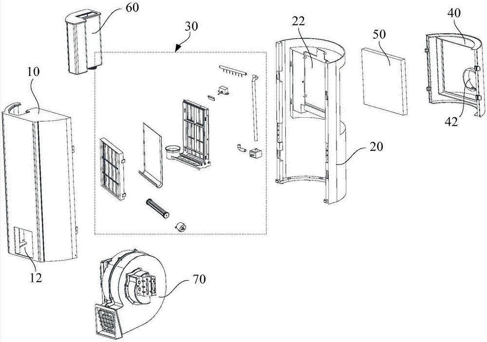
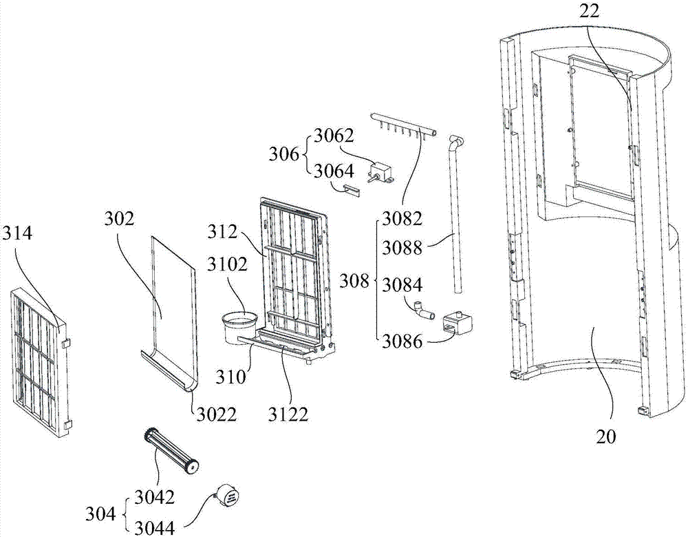
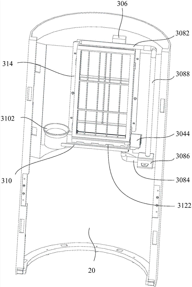
[0055] Refer below Figure 1 to Figure 4 An air conditioner according to some embodiments of the present invention will be described.

[0056] Such as Figure 1 to Figure 4 As shown, the embodimen...


PUM


Abstract

The invention provides an air conditioner and a humidifying control method and system. The humidifying control method and system are used for the air conditioner. The air conditioner comprises a humidifying assembly. The humidifying assembly comprises a water absorption piece, a drive assembly, a detection device, a spraying assembly and a water tank. The drive assembly drives the water absorption piece to make reciprocating movement in a semi-annular trajectory of a top end opening. The water tank is formed in the bottom of the water absorption piece to allow the water absorption piece to absorb water. The spraying assembly supplements wetness for the water absorption piece. The detection device is located at the top end of the water absorption piece, when the water absorption piece moves into the induction area of the detection device, the drive assembly is controlled by the detection device to drive the water absorption piece to move in the reverse direction, the processes are preformed in a reciprocating manner, and continuous humidifying is achieved. Under the action of the airflow, evaporation of water on the water absorption is accelerated; and meanwhile, due to the fact that heat is absorbed through evaporation, the temperature of the airflow is lowered, then the airflow flows back into a room carrying water vapor, and the effect of humidifying indoor air is achieved while the effect of lowering the temperature of the indoor air is also achieved.

Description

technical field [0001] The present invention relates to the technical field of household appliances, in particular to an air conditioner, a humidification control method and a humidification control system. Background technique [0002] At present, air conditioners only have cooling or heating functions, that is, they can only adjust the indoor temperature, but cannot adjust the indoor humidity. Especially in winter, when the air conditioner is used, the indoor temperature is high and the indoor air is very dry. Living indoors for a long time will reduce the comfort of users; in order to solve the above problems, users often place humidifiers indoors to increase the indoor humidity. However, the range that humidification can reach is limited, and the efficiency of humidifiers is low. It is only suitable for personal use, and cannot satisfy the air humidification of a large space, and most of the existing humidifiers are ultrasonic humidifiers, which use ultrasonic vibrators ...

Claims


Application Information

Patent Timeline
Patent Type & Authority Applications(China)
IPC IPC(8): F24F1/00F24F11/02F24F11/00F24F13/28
CPCF24F1/00F24F13/28
Inventor 闫长林陈良锐
Owner GD MIDEA AIR-CONDITIONING EQUIP CO LTD
Learn More