
Dynamic length regulation device for refrigeration capillary tubes

A dynamic adjustment, capillary technology, used in refrigerators, refrigeration components, refrigeration and liquefaction, etc., can solve the problems of low efficiency, not necessarily finding the optimal length, and consuming a lot of manpower, material resources and time, and achieves high efficiency. Effect

Pending Publication Date: 2017-11-24
CHINA ELECTRONICS TECH GROUP CORP NO 16 INST
View PDF8 Cites 3 Cited by
  • Summary
  • Abstract
  • Description
  • Claims
  • Application Information

AI Technical Summary

Problems solved by technology

[0003] However, the length of the capillary in the refrigeration system is generally obtained by trial and error, or based on the known length and diameter of the capillary, the length of the capillary with different diameters that can achieve the same effect can be determined by measuring the pressure difference and flow rate between the inlet and outlet. , these methods require a large number of experiments and tests, and sometimes require repeated welding and desoldering, which consumes a lot of manpower, material resources and time, and does not necessarily find the best length
Moreover, once the capillary tube is welded and installed in the refrigeration system, its length cannot be changed, which brings great difficulties in the process of debugging the performance of the refrigeration system, requiring repeated welding and desoldering, low efficiency and high risk of pipeline blockage, especially for new research in the system

Method used


Image

  • Dynamic length regulation device for refrigeration capillary tubes
  • Dynamic length regulation device for refrigeration capillary tubes

Examples


Embodiment Construction

[0014] The present invention will be further described below in conjunction with accompanying drawing:

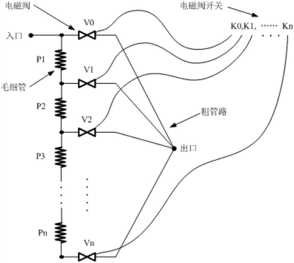
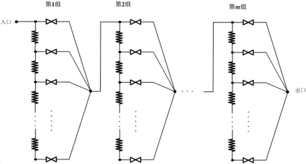
[0015] Such as figure 1 As shown, n capillaries of equal length are connected in series, and then connected with n+1 solenoid valves such as figure 1 connected as shown to form a single assembly. Such as figure 2 The overall application shown can be composed of several components connected in series to achieve more length combinations.

[0016] The capillary is a metal tube with an inner diameter in the range of 0.4 mm to 2 mm, which plays a throttling role. The length and inner diameter of each section of capillary in each module are the same, and the lengths of capillary in different modules are different. The thick pipe is a pipe with a larger inner diameter, which has a small flow resistance and does not have a throttling effect, but only serves as a pipe connection. The solenoid valve is normally closed, and the solenoid valve corresponds to the solenoid valve on...


PUM

PropertyMeasurementUnit
The inside diameter ofaaaaaaaaaa

Abstract

The invention relates to a dynamic length regulation device for refrigeration capillary tubes. The dynamic length regulation device comprises multiple assemblies connected in series. An outlet of each previous assembly is connected with an inlet of the corresponding next assembly. Each assembly comprises the n corresponding capillary tubes which are connected in series and have the equal length, n+1 electromagnetic valves and n+1 electromagnetic valve switches. Inlets of every n+1 corresponding electromagnetic valves are connected with inlets of the corresponding n capillary tubes and an outlet of the last corresponding capillary tube. Outlets of every n+1 corresponding electromagnetic valves are connected together to be used as the outlet of the whole corresponding assembly. Each electromagnetic valve is controlled to be opened and closed through the corresponding electromagnetic valve switch. The capillary tubes are connected through thick pipelines. The electromagnetic valves and the capillary tubes are connected through thick pipelines. The electromagnetic valves are connected through thick pipelines. According to the dynamic length regulation device, the series connection combined method similar to the method in circuits is adopted, various dynamic combinations are achieved by controlling the multiple capillary tubes through the valves, and the specific capillary tube length can be achieved without welding the pipelines again.

Description

technical field [0001] The invention relates to the technical field of refrigeration and low temperature engineering, in particular to a dynamic adjustment device for the length of a refrigeration capillary tube. Background technique [0002] For household refrigerators, portable mobile refrigerators, small air conditioners, chillers and other equipment using vapor compression refrigeration systems and low-temperature devices such as throttling refrigerators and pulse tube refrigerators, capillary tubes are an important part of the refrigeration cycle and can play a good role. It has the advantages of simple structure and high reliability. [0003] However, the length of the capillary in the refrigeration system is generally found by trial and error, or based on the known length and diameter of the capillary, the length of the capillary with different diameters that can achieve the same effect can be determined by measuring the pressure difference and flow rate between the i...

Claims


Application Information

Patent Timeline
IPC IPC(8): F25B41/04F25B41/06F25B41/20F25B41/37
CPCF25B2600/25F25B41/37F25B41/20
Inventor 张文千
Owner CHINA ELECTRONICS TECH GROUP CORP NO 16 INST
Learn More