Supercharge Your Innovation With Domain-Expert AI Agents!

Compressing and smelting device for metal casting

A technology of metal casting and pressing plate, which is applied in the direction of crucible furnace, furnace, lighting and heating equipment, etc. It can solve the problems of poor compression effect, single vertical compression, uneven temperature, etc., to improve the compression effect, increase the compression speed, and heat stable effect

Inactive Publication Date: 2017-11-24
湖州市下昂多联铸造有限公司
View PDF0 Cites 3 Cited by
  • Summary
  • Abstract
  • Description
  • Claims
  • Application Information

AI Technical Summary

Problems solved by technology

[0002] Metal casting is the process of smelting metal into a liquid that meets certain requirements in a furnace and pouring it into a mold, cooling and solidifying, and cleaning to obtain a casting with a predetermined shape, size and performance. Some metal scraps can also be collected for the next metal casting, and these scraps generally need to be compressed into blocks to reduce the gaps between the scraps and put them into the crucible for casting. However, the existing The debris compression device is generally a single vertical compression, the efficiency of compression into blocks is relatively slow, and it is inconvenient to extract the finished product blocks, and the compressed shape is also inconvenient for melting in a melting furnace. The effect is poor; and when metal is smelted, it is generally used to put the metal block into the crucible, and then put it into the burning coal furnace device for heating until the metal in the crucible is smelted into liquid, and put it in the coal furnace When the coal is burned, it is affected by external forces such as wind, so that the temperature in the furnace is uneven, and the metal is heated unevenly in the crucible, and the combustion of coal and other substances will produce toxic gases and waste solids, and it will also pollute the environment.
Therefore, the existing compression smelting devices used in the foundry industry have the problems of slow efficiency, poor compression effect, uneven heating and environmental pollution.

Method used


Image

  • Compressing and smelting device for metal casting
  • Compressing and smelting device for metal casting
  • Compressing and smelting device for metal casting

Examples


Embodiment Construction

[0020] The present invention will be further described below in conjunction with the accompanying drawings and embodiments, but not as a basis for limiting the present invention.

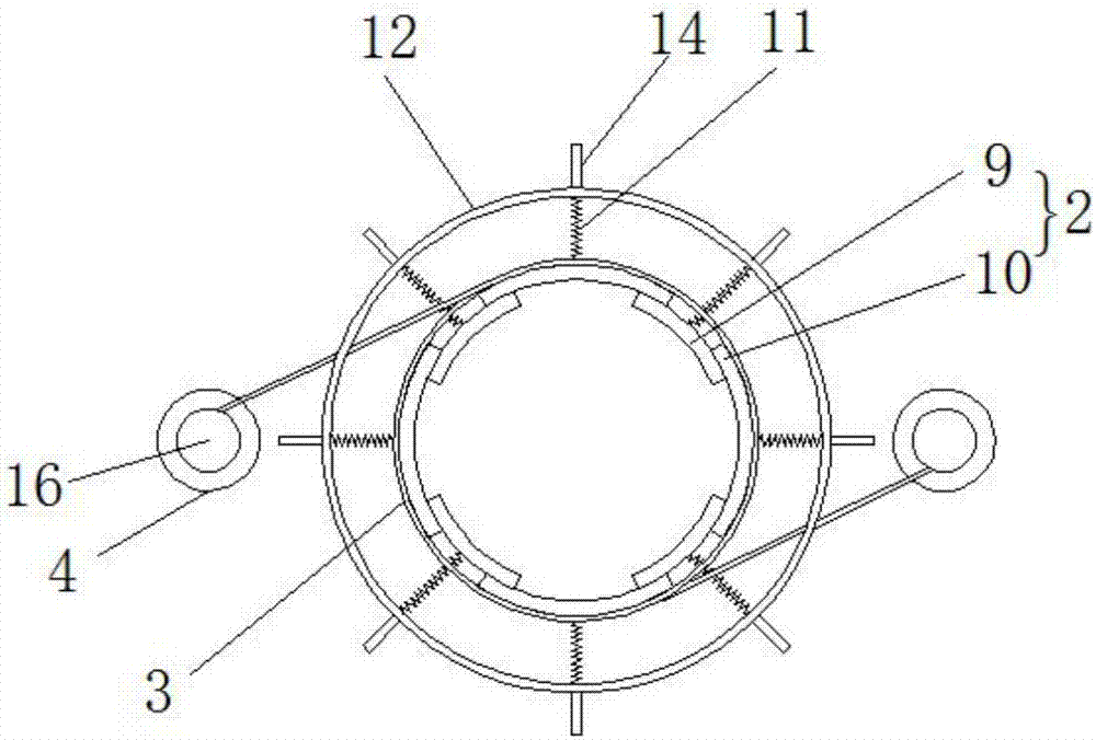
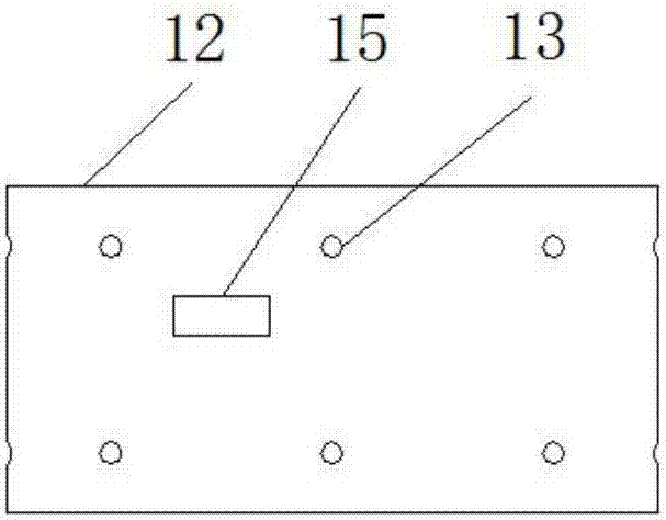
[0021] Example. A compression smelting device for metal casting, consisting of Figures 1 to 7 As shown, it includes a frame 1, and the frame 1 is provided with an extruding plate 2; the outer ring of the extruding plate 2 is wound with a tightening rope 3, and both sides of the tightening rope 3 are connected with a motor 4; the extruding plate 2 The upper end is provided with a hydraulic cylinder 5, and the lower end of the extrusion plate 2 is connected with a lifting plate 6; one side of the lifting plate 6 is provided with a push rod 7, and the other side is provided with a chute 8, and one side of the chute 8 is provided with a conveyor belt 21; One side of the frame 1 is provided with a furnace shell 22, the inner wall of the furnace shell 22 is provided with a heating element 23, and an ins...


PUM


Abstract

The invention discloses a compression smelting device for metal casting, which comprises a frame (1), on which an extruding plate (2) is arranged; on the extruding plate (2), a binding rope (3) is arranged ), a hydraulic cylinder (5) and a lifting plate (6); one side of the lifting plate (6) is provided with a chute (8), and one side of the chute (8) is provided with a conveyor belt (21); the frame (1) A furnace shell (22) is provided on one side, and a heating element (23), an insulating layer (24) and a crucible (25) are arranged in the furnace shell (22), and a furnace bottom plate (26), a rotating A plate (27) and a lifting device (28); the furnace shell (22) is externally connected with a furnace cover (29) and a control system (30). The invention can not only improve the efficiency, improve the compression effect, make the heating more uniform and protect the environment, but also has the advantages of good structural stability, balanced binding force, good load-bearing capacity, good mechanism flexibility, labor saving and high safety. The advantages.

Description

technical field [0001] The invention relates to a compression melting device for metal casting in the foundry industry. Background technique [0002] Metal casting is the process of smelting metal into a liquid that meets certain requirements in a furnace and pouring it into a mold, cooling and solidifying, and cleaning to obtain a casting with a predetermined shape, size and performance. Some metal scraps can also be collected for the next metal casting, and these scraps generally need to be compressed into blocks to reduce the gaps between the scraps and put them into the crucible for casting. However, the existing The debris compression device is generally a single vertical compression, the efficiency of compression into blocks is relatively slow, and it is inconvenient to extract the finished product blocks, and the compressed shape is also inconvenient for melting in a melting furnace. The effect is poor; and when metal is smelted, it is generally used to put the metal...

Claims


Application Information

Patent Timeline
IPC IPC(8): F27B14/06F27B14/08F27B14/14F27B14/20
CPCF27B14/06F27B14/0806F27B14/14F27B14/20
Inventor 潘阿五
Owner 湖州市下昂多联铸造有限公司
Features
  • R&D
  • Intellectual Property
  • Life Sciences
  • Materials
  • Tech Scout
  • Unparalleled Data Quality
  • Higher Quality Content
  • 60% Fewer Hallucinations
Learn More