
Power frequency modulation series resonance test system and test method thereof

A series resonance, test system technology, applied in the test circuit, test ship construction, test dielectric strength and other directions, can solve the problems of damage to the sample, unable to drive the power factor transmitter, test failure, etc., to improve the test efficiency. Effect

Inactive Publication Date: 2017-11-24
江苏锦秀高压电器有限公司
View PDF4 Cites 10 Cited by
  • Summary
  • Abstract
  • Description
  • Claims
  • Application Information

AI Technical Summary

Problems solved by technology

[0003] At present, the air gap adjustable reactor in the power frequency series resonance system for high voltage test on the market basically ignores the calculation of the maximum inductance in the electromagnetic calculation link, and the search for the resonance point in the tuning process also depends on the experience of the operator, and it is applied in time. The power factor transmitter is used to track the resonance point, and the linearity is poor. In the boost stage, because the system current is basically in the milliampere level, the power factor transmitter cannot be driven at all. These problems lead to the low degree of automation of the entire system. At the resonance point Resonant overvoltage or detuning is prone to occur nearby, resulting in test failure or damage to the test product

Method used


Image

  • Power frequency modulation series resonance test system and test method thereof
  • Power frequency modulation series resonance test system and test method thereof
  • Power frequency modulation series resonance test system and test method thereof

Examples


Embodiment

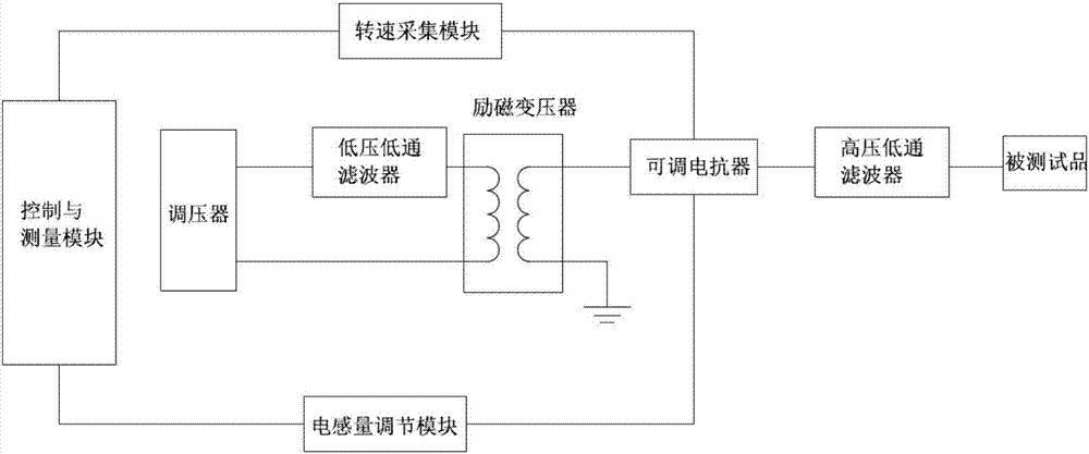
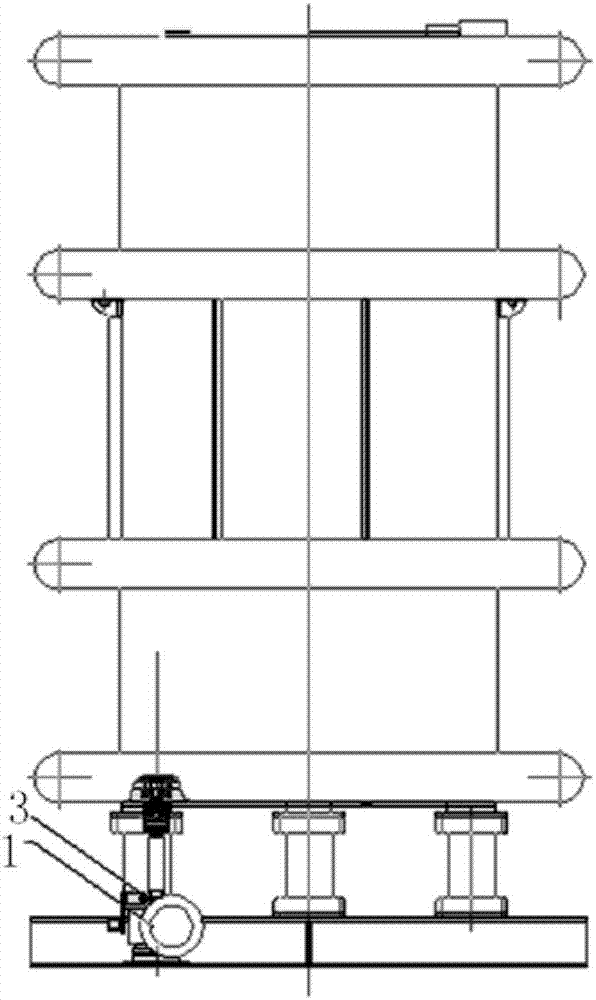
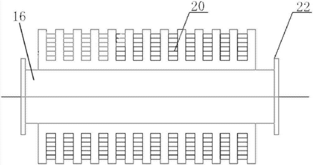
[0032] Such as figure 1 As shown, this embodiment discloses a power frequency induction series resonance test system, including a voltage regulator, an excitation transformer, an adjustable reactor, a speed acquisition module, an inductance adjustment module, and a control and measurement module; The transformer is connected to the primary side of the excitation transformer to provide voltage for the primary side of the excitation transformer; the secondary side of the above-mentioned excitation transformer is connected to an adjustable reactor, and the above-mentioned adjustable reactor is connected to an external tested product that requires power frequency voltage; the above-mentioned inductance adjustment The module is used to adjust the inductance of the adjustable reactor; the above-mentioned speed acquisition module is used to collect the motor speed of the adjustable reactor and feed it back to the control and measurement module. The above-mentioned control and measurem...


PUM


Abstract

The invention provides a power frequency modulation series resonance test system. The system comprises a voltage regulator, an excitation transformer, an adjustable reactor, a rotating speed acquisition module, an inductance value adjusting module and a control and measurement module. The voltage regulator provides a voltage for a primary side of the excitation transformer. A secondary side of the excitation transformer is connected to the adjustable reactor. The adjustable reactor is connected to an externally-connected detected test object which needs a power frequency voltage. The inductance value adjusting module is used for adjusting an inductance value of the adjustable reactor. The rotating speed acquisition module is used for collecting a motor rotation speed of the adjustable reactor and feeding back to the control and measurement module. The control and measurement module drives the inductance value adjusting module to adjust the inductance value of the adjustable reactor. A whole system carries out resonance under a power frequency. By using the power frequency modulation series resonance test system, the inductance value can be positioned in a high precision mode and fine tuning of the voltage is realized; and through cooperating with the excitation transformer, the voltage regulator, control and measurement equipment and the like, a voltage withstanding test of a capacitance test object under a condition of 500KV and below and an automation test of partial discharge can be completed.

Description

technical field [0001] The invention relates to a power frequency series resonance test system and a test method thereof, in particular to a power frequency series resonance test system with high-precision positioning of inductance and a test method thereof. Background technique [0002] In the power test, the test of the capacitive test product can only be carried out at the power frequency of 50Hz, because the test product does not have the equivalent characteristics of the power frequency at a frequency different from the power frequency or the measured data is relatively different from the power frequency. , the test of this kind of test product must be carried out under power frequency. At this time, we can only make it resonate under power frequency by changing the inductance, capacitance or both at the same time. This kind of resonance is called power frequency series resonance. [0003] At present, the air gap adjustable reactor in the power frequency series resonanc...

Claims


Application Information

Patent Timeline
IPC IPC(8): G01R31/14G01R31/16
CPCG01R31/14G01R31/16
Inventor 张秀江甘鹏汤春荣李威
Owner 江苏锦秀高压电器有限公司
Learn More