
Vibration mode parameter identification method based on state observer

A technology of state observer and vibration mode, applied in vibration testing, instruments, measuring devices, etc., can solve problems such as poor analysis results, achieve accurate identification, strong method versatility, and simple realization

Inactive Publication Date: 2017-11-24
DALIAN UNIV OF TECH
View PDF3 Cites 15 Cited by
  • Summary
  • Abstract
  • Description
  • Claims
  • Application Information

AI Technical Summary

Problems solved by technology

[0003] Traditional modal parameter identification methods generally use the method of frequency-domain fitting of vibration signals to determine modal parameters, such as Mark H.Richardson and David L.Formenti in "Parameter estimation from frequency response measurements using rational fraction polynomials (twenty years of progress )[A].Proceedings of 20th International Modal Analysis Conference[C].IMAC,Los Angeles:Society for Experimental Mechanics,2002.373-382 "proposed orthogonal polynomial identification method, which is a classic and commonly used modal parameter identification method , this method needs to select a relatively high order of the identification mode to ensure the accuracy, but when the order of the identification mode is higher than the order of the real mode, false modes will appear, and the removal of false modes generally requires Based on experience, and the analysis effect is not good for vibration modes with similar frequencies

Method used


Image

  • Vibration mode parameter identification method based on state observer
  • Vibration mode parameter identification method based on state observer
  • Vibration mode parameter identification method based on state observer

Examples


Embodiment Construction

[0046] The specific implementation of the present invention will be described in detail below in conjunction with the accompanying drawings and technical solutions.

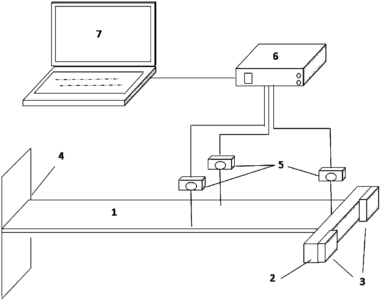
[0047] Such as figure 2 As shown, the free vibration experiment system is set up first. The free vibration experiment system is composed of aluminum cantilever beam 1, aluminum counterweight 2, steel counterweight 3, fixed end 4, laser displacement sensor group 5, data acquisition card 6 and computer 7; The laser displacement sensor group 5 is used as a measuring element to build a cantilever beam free vibration experimental device. The laser displacement sensor measures the displacement signal of the cantilever beam, and after the A / D conversion is performed by the data acquisition card 6, it is transmitted to the computer 7. The displacement signal is processed to obtain the precise modal parameters of the cantilever beam.

[0048] figure 1 It is a flow chart of the vibration modal parameter identification m...


PUM


Abstract

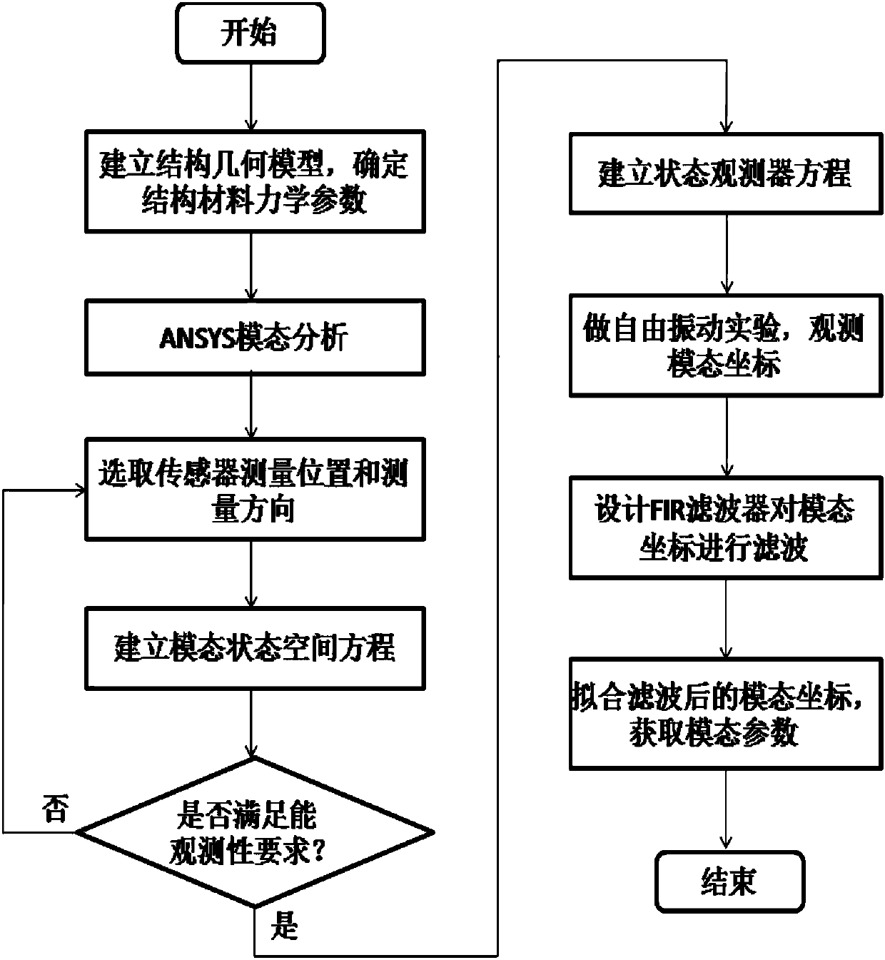
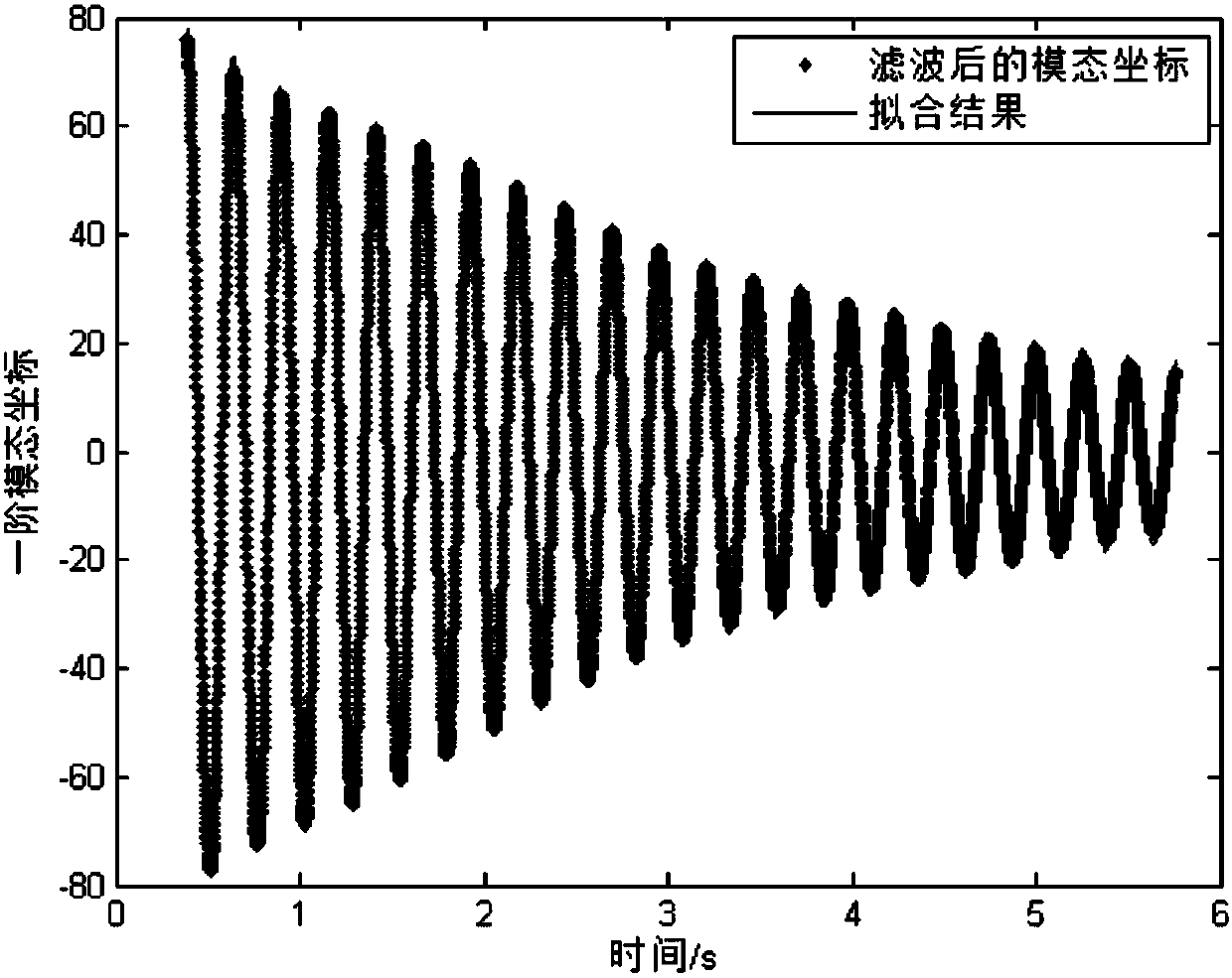
The invention provides a vibration mode parameter identification method based on a state observer, belongs to the field of vibration mode analysis, and relates to the vibration mode parameter identification method based on the state observer. The method aims at a specific structure and a concerned vibration order, firstly an ANSTS mode is used for analysis, the vibration frequencies and vibration modes of all orders are approximately obtained, then a free vibration experiment is established, a plurality of non-contact high-resolution laser displacement sensors are adopted to measure structure displacement signals, and a mode state space equation and a state observer of the whole system are built. After the state observer is adopted to obtain free vibration mode coordinates of all orders, an FIR filter is adopted to filter out interference signals. Finally, the sinusoidal function with exponential attenuation is adopted to fit filtered mode coordinates, and the precise frequency and damping ratio of vibration of all orders are obtained. The vibration mode parameter identification method is easy to achieve, accurate in identification, high in universality, and suitable for vibration mode parameter identification of various structures.

Description

technical field [0001] The invention belongs to the field of vibration modal analysis, and relates to a vibration modal parameter identification method based on a state observer. Background technique [0002] The vibration problem of mechanical structures is a problem that must be considered in many engineering practices. According to vibration mechanics, the vibration of structures is composed of infinite vibration modes. Among them, the first few vibrations belong to the important mechanical properties of mechanical structures. Especially in the field of aerospace vibration control, the natural frequency and damping ratio of each order of vibration are important modal parameters, which have an important impact on the flight speed and wind resistance of the aircraft. After geometrically modeling the mechanical structure and obtaining the corresponding material mechanical parameters, the modal analysis of the structure can be performed using finite element analysis software,...

Claims


Application Information

Patent Timeline
Patent Type & Authority Applications(China)
IPC IPC(8): G06F17/50G01M7/02G01H17/00
CPCG01H17/00G01M7/02G06F30/23
Inventor 盛贤君周少征
Owner DALIAN UNIV OF TECH
Learn More