360° detection sensor and detection method based on area array ccd/cmos

A CMOS sensor and detection sensor technology, applied in the field of sensors, can solve the problems that cannot be eliminated, increase the complexity of the system, restrict the service life, etc., and achieve the effect of strong anti-interference ability in the environment

Active Publication Date: 2020-02-18
天津宜科自动化股份有限公司
View PDF5 Cites 0 Cited by
  • Summary
  • Abstract
  • Description
  • Claims
  • Application Information

AI Technical Summary

Problems solved by technology

Since every turn, only the area currently covered by the sensor can be detected, and other uncovered areas cannot be detected, and full-time 360° detection cannot be realized. Even if the scanning frequency of the scanning motor is increased, this problem cannot be eliminated.
The scanning motor and transmission part not only increases the complexity of the system, but also the mechanical life of this part restricts the service life of the whole system

Method used


Image

  • 360° detection sensor and detection method based on area array ccd/cmos
  • 360° detection sensor and detection method based on area array ccd/cmos
  • 360° detection sensor and detection method based on area array ccd/cmos

Examples


Embodiment 1

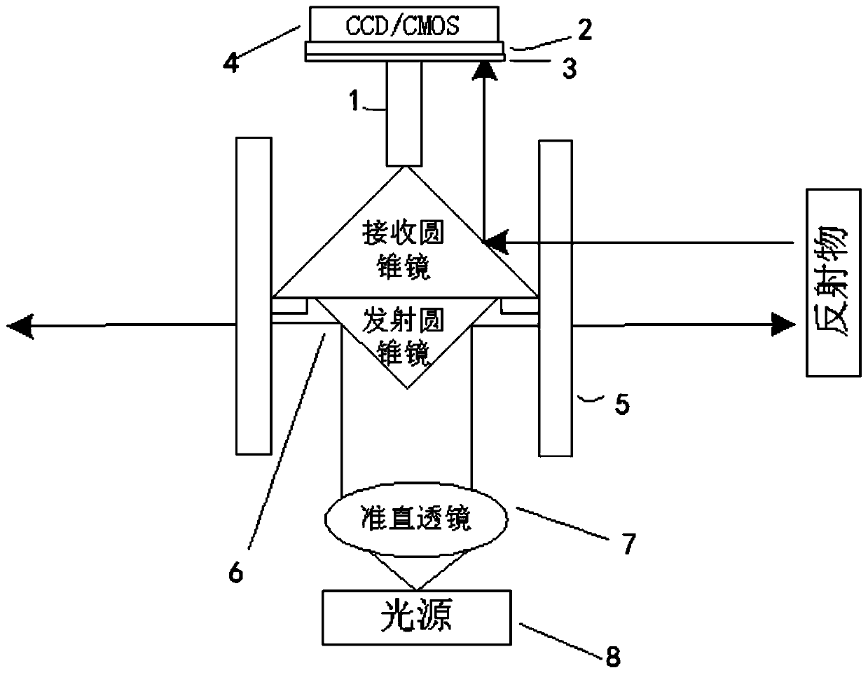
[0024] Such as figure 1 Shown is a specific embodiment of the application. This embodiment comprises area array CCD / CMOS sensor 4, conical mirror 6, and conical mirror 6 comprises emitting conical mirror, receiving conical mirror, light-shielding cylinder 1, light source 8, collimating lens 7, narrow-band optical filter 2, cylindrical window 5 (on the one hand, this component plays a supporting role as a structural component, and on the other hand, it is used as an optical component to transmit light), a circular aperture stop 3, an image processor unit module, a light source driving module, a signal output unit, a display unit module, etc. The area array CCD / CMOS sensor 4, the light source driving module, the signal output unit, and the display unit module are all connected to the image processing unit module, and the light source is connected to the light source driving module. The emitting light source shoots to the conical tip of the emitting conical mirror, the circular ...

Embodiment 2

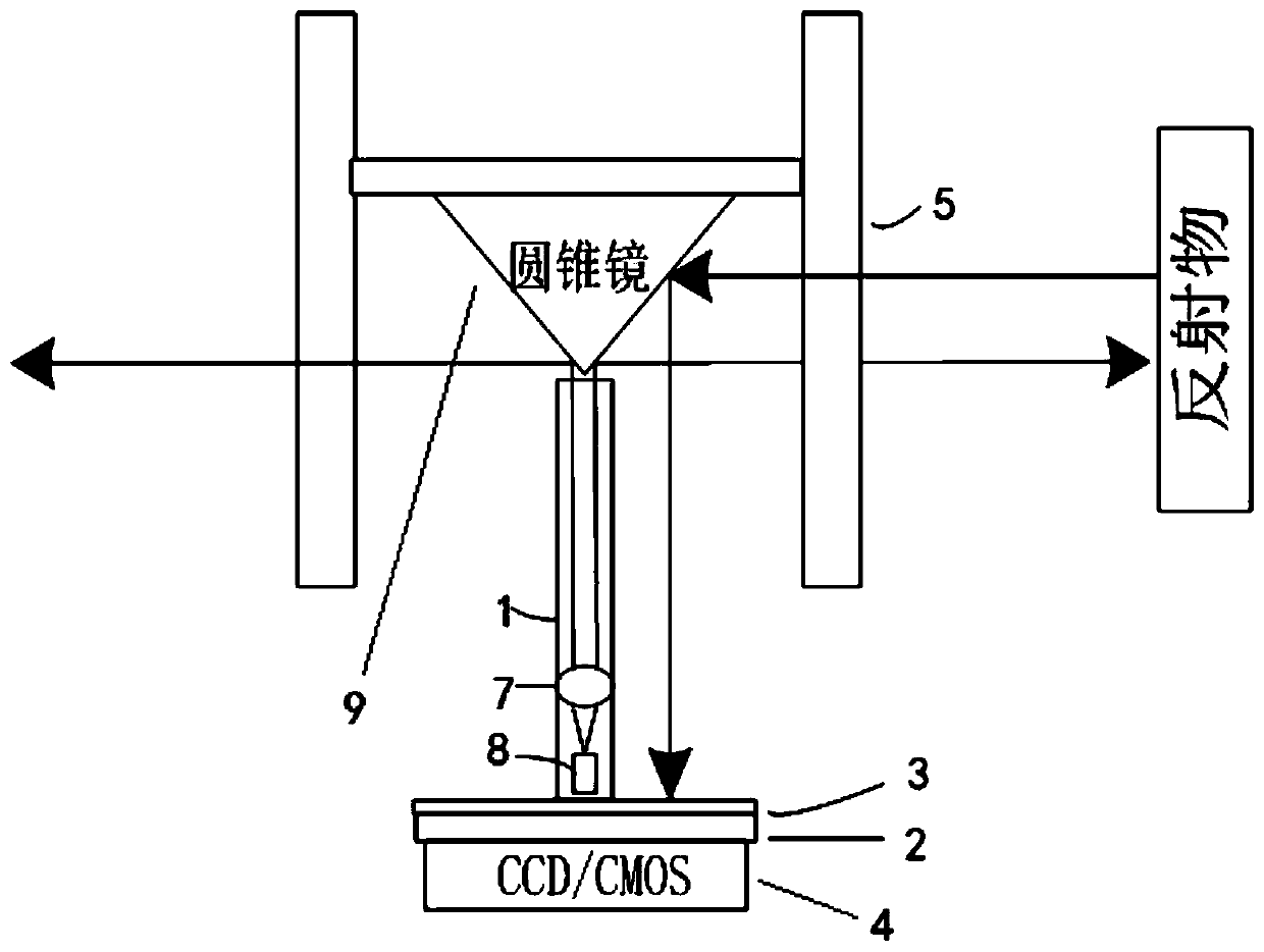
[0026] Such as figure 2 As shown, the difference from Embodiment 1 is that the conical mirror 9 is a single conical mirror, the light source 8 is arranged on one side of the conical mirror 6, the conical mirror 6 is arranged in the cylindrical window 5, and the shading tube 1 is covered by the light source 8, Around the collimating lens 7 and on one side of the light-shielding tube 1 are sequentially arranged a circular aperture stop 3 , a filter 2 , and an area array CCD / CMOS sensor 4 , and the others are the same.

[0027] It should be noted that, in the above-mentioned embodiments 1 and 2, the emitting light source can be a laser light source or LED light source of any wavelength band, and can be red light, infrared light, green light, blue light, etc.; the emitting light source is collimated emitted light , is an approximately parallel beam. The emission of light to obtain a fan or circumference is obtained through a conical mirror. In embodiment 1, the conical half-ang...


PUM


Abstract

The invention discloses a 360° detection sensor based on an area array CCD / CMOS and a detection method, including an area array CCD / CMOS sensor, a conical mirror, a light-shielding tube, a light source, a collimating lens, an optical filter, a cylindrical window, Circular aperture diaphragm, after the light source passes through the collimating lens, after being emitted through the conical mirror, it is emitted through the cylindrical window, and after meeting the reflector, it is reflected by the reflector through the conical mirror, and then emitted through the conical mirror, and the light passing through the circular aperture Diaphragm, filter reflected to the area array CCD / CMOS sensor. Correspondingly, a detection method based on the above-mentioned area array CCD / CMOS 360° detection sensor is also provided. The present invention realizes 360° no dead angle detection, realizes full coverage detection of one machine, or area detection, and can be used for perimeter collision avoidance , area security, contour detection, contour detection, angle tilt and other applications. In addition, the method of image difference is adopted, which has strong anti-interference ability to the environment.

Description

technical field [0001] The invention relates to the technical field of sensors, in particular to a 360° detection sensor and a detection method based on an area array CCD / CMOS. Background technique [0002] The core components of the existing 360° sensors are ordinary photoelectric sensors and mechanical parts that can drive ordinary sensors to rotate at high speed. Ordinary photoelectric sensors can only detect objects within a small angle range in the horizontal direction. To achieve 360° detection, a 360° scanning motor is required to drive the photoelectric sensor to rotate and scan through the transmission part. Since every turn, only the area currently covered by the sensor can be detected, and other uncovered areas cannot be detected, and full-time 360° detection cannot be realized. Even if the scanning frequency of the scanning motor is increased, this problem cannot be eliminated. . The scanning motor and transmission part not only increases the complexity of the ...

Claims


Application Information

Patent Timeline
Patent Type & Authority Patents(China)
IPC IPC(8): H04N5/225H04N5/374
CPCH04N23/55H04N23/54H04N25/76
Inventor 代红林
Owner 天津宜科自动化股份有限公司
Why Eureka
Try Eureka