Bearing intelligent temperature control heater

An intelligent temperature control and heater technology, applied in induction heating, induction heating devices, metal processing and other directions, can solve the problems of difficult access to bearings, complex structure, waste of resources, etc., to achieve low cost, accurate and controllable temperature, The effect of high heating efficiency

Active Publication Date: 2020-05-12
CHINA THIRD METALLURGICAL GRP
View PDF8 Cites 0 Cited by
  • Summary
  • Abstract
  • Description
  • Claims
  • Application Information

AI Technical Summary

Problems solved by technology

"This patent is applicable to the heating operation of a single bearing. The existing problems are: the structure is relatively complicated, the heated bearing is not easy to take, and if there is a problem that it is easy to cause pollution and waste resources.

Method used


Image

  • Bearing intelligent temperature control heater
  • Bearing intelligent temperature control heater
  • Bearing intelligent temperature control heater

Examples


Embodiment 1

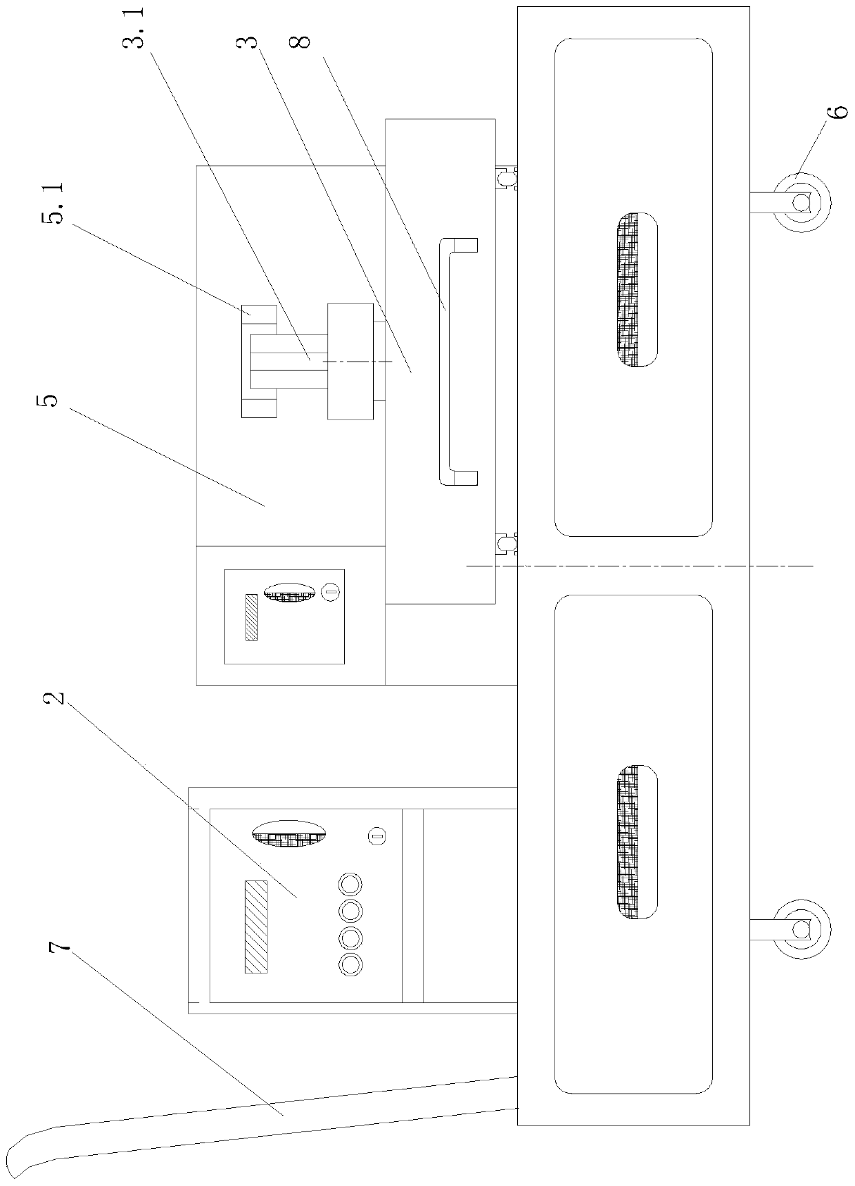
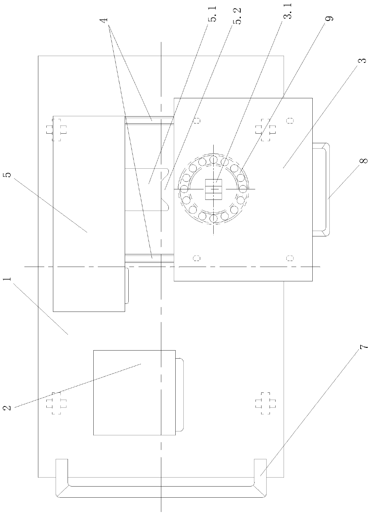
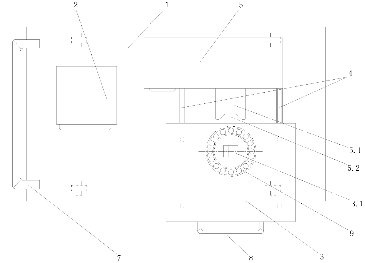
[0019] Such as figure 1 , figure 2 As shown, the present invention includes a platform 1, a control center 2, a bearing shelving trolley 3, a track 4 and a bearing electromagnetic heating device 5. The control center 2 is arranged on the left side of the platform 1, the bearing electromagnetic heating device 5 is arranged at the rear part of the right side of the platform 1, and the control center 2 and the bearing electromagnetic heating device 5 are electrically connected. Bearing shelving dolly 3 is located at the front portion of the right side of platform 1. The bearing electromagnetic heating device 5 is provided with a bump 5.1 for electromagnetic heating, and the bump 5.1 has two pieces, one of which is located above the other bump 5.1; the front part of the bump 5.1 is provided with a trapezoidal The distance between the notch 5.2, the lower surface of the upper projection 5.1 and the upper surface of the lower projection 5.1 is greater than the axial thickness of ...

Embodiment 2

[0022] The difference between the second embodiment and the first embodiment is that the platform push handle 7 in this embodiment is a T-shaped connecting rod, the lower end of which is connected to the platform 1, and the upper end is a handshake push handle, which is higher than the control handle. The upper end of both the center 2 and the bearing electromagnetic heating device 5 is higher, and the upper end of the handshake push handle is located on the left side of the platform 1 . In addition, the trolley pusher handle 8 provided at the front end of the bearing shelving trolley 3 is also horizontally T-shaped, consisting of a horizontal bar parallel to the front end of the bearing shelving trolley 3 and a horizontal vertical bar perpendicular to the front end of the bearing shelving trolley 3, T The free end of the shaped vertical bar links to each other with the front end of bearing shelving dolly 3.

Embodiment 3

[0024] The difference between the third embodiment and the first embodiment is that, in the third embodiment, the platform pushing handle 7 includes a drawstring storage column fixed on the left side of the platform 1 and a drawstring fixedly connected to the drawstring storage column at one end. When the bearing is heated, the stay rope is wound on the stay rope storage post. When the platform 1 is to be moved, untie the winding of the stay rope to the stay rope storage post, and then pull the stay rope.


PUM


Abstract

The invention discloses an intelligent temperature control heater for a bearing. The heater comprises a platform, a control center, a bearing placing trolley, a track and an electromagnetic heating device for the bearing, wherein the control center is electrically connected to the electromagnetic heating device for the bearing; the bearing placing trolley is arranged at the front part of the right side of the platform; an upper lug and a lower lug are arranged on the electromagnetic heating device for the bearing; a trapezoidal recess is arrange at the front parts of the lugs; the distance between the upper lug and the lower lug is greater than the axial thickness of the bearing; an upright column used for placing the bearing is arranged on the bearing placing trolley; and the bearing is arranged on the center line of the back bearing on the upright column and is parallel to the perpendicular bisector of the bottom surface of the recess. The upper end face and the lower end face of the bearing are respectively arranged below the upper lug and above the lower lug. The upright column forms a movable end matched with the lugs to carry out electromagnetic heating on the bearing. The track moves back and forth, the bearing placing trolley is supported on the track in a rolling manner, and the front end of the track stretches out of the front edge of the platform. The control center is electrically connected to the electromagnetic heating device for the bearing. The platform is arranged on trolley wheels, and a movable structure used for moving the platform is arranged on the trolley wheels.

Description

technical field [0001] The invention relates to a bearing heating device, in particular to an intelligent temperature-controlled heater for a bearing. Background technique [0002] Bearings, gears, couplings, etc. on mechanical equipment are mostly connected by interference fit during installation, requiring the workpiece to be heated to install. The traditional heating method is mainly to use gas welding or oil heating. The disadvantage of gas welding is that the heating is not enough. The average temperature is not easy to control, and the disadvantage of oil heating is that the temperature is not easy to control, which is easy to cause pollution and waste resources. [0003] Application number: 201620879484.6, authorized announcement number: CN205968000U, titled "A bearing heating device with bearing fixing mechanism" provides another bearing heating device: "Including trusses, support columns, oil tanks, heating devices and bearing hoisting devices, The bearing hoisting...

Claims


Application Information

Patent Timeline
Patent Type & Authority Patents(China)
IPC IPC(8): H05B6/10B23P11/02
CPCB23P11/025H05B6/10
Inventor 刘长富
Owner CHINA THIRD METALLURGICAL GRP
Why Eureka
Try Eureka