Cleaning device for petrochemical pipeline

A pipeline cleaning and petrochemical technology, applied in the direction of cleaning hollow objects, cleaning methods and utensils, chemical instruments and methods, etc., can solve the problems of reducing pipeline service life, pipeline blockage, pipeline damage, etc., and achieves simple structure and easy use. Convenience and clear cleaning effect

Inactive Publication Date: 2017-11-28
郑州联慧双创知识产权代理有限公司
View PDF8 Cites 11 Cited by
  • Summary
  • Abstract
  • Description
  • Claims
  • Application Information

AI Technical Summary

Problems solved by technology

[0002] For petrochemical raw material transportation equipment, it is necessary to clean the petrochemical pipelines. During the process of transporting petrochemical raw materials, there will be residue or oil stains, and some petrochemical pipelines will have rust inside due to long-term use. These Residual dross or oil stains and rust will affect the delivery volume of the pipeline, and even cause the pipeline to be blocked. Therefore, it is very important to provide a cleaning device for cleaning the inside of the petrochemical pipeline. At present, the existing petrochemical cooling pipe descaling method, Generally, the pipeline is cleaned through the principle of chemical reaction, which is easy to cause damage to the pipeline, thereby reducing the service life of the pipeline. In summary, in view of the defects of the existing technology, a petrochemical cooling pipe cleaning is especially needed Special tools, the existing pipe cleaners only use brushes and high-pressure water to clean, but cannot completely clean up the oil stains in the petrochemical pipelines and the rust stains fixed on the inside of the pipelines.

Method used


Image

  • Cleaning device for petrochemical pipeline
  • Cleaning device for petrochemical pipeline

Examples


Embodiment Construction

[0016] In order to further understand the invention content, characteristics and effects of the present invention, the following examples are listed hereby, and detailed descriptions are as follows in conjunction with the accompanying drawings.

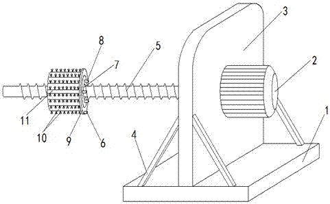
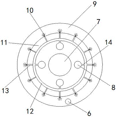
[0017] Combine below Figure 1-2 The petrochemical pipeline cleaning device of the present invention is described in detail: a petrochemical pipeline cleaning device, including a base 1, a motor 2, a mounting plate 3, a support rod 4, a screw rod 5, a brush 10 and a cleaning cylinder 11. The middle position above the base 1 is provided with a mounting plate 3, the two sides of the mounting plate 3 are provided with support rods 4, the other end of the support rod 4 is fixed on the base 1, and the middle position of one side of the mounting plate 3 is provided with a motor 2. A screw rod 5 is provided in the middle of the other side of the installation plate 3, and the screw rod 5 and the motor 2 are positioned symmetrically. The screw...


PUM


Abstract

The invention relates to a cleaning device for a petrochemical pipeline. The cleaning device comprises a base, a motor, an installation plate, support rods, a screw rod, brushes and a cleaning cylinder. The installation plate is arranged at the middle position of the top of the base. The support rods are arranged on the two sides of the installation plate. The other ends of the support rods are fixed to the base. The motor is arranged at the middle position of one side of the installation plate. The lead screw is arranged at the middle position of the other side of the installation plate. The lead screw and the motor are symmetrically arranged in position. By means of the cleaning device for the petrochemical pipeline, due to the cleaning cylinder arranged on the lead screw in a sleeving manner, the cleaning cylinder can be pushed to move forward in the pipeline to conduct cleaning simply through rotation of the motor, the cleaning cylinder can be taken out only through reverse rotation of the motor during taking-out, and meanwhile the pipeline is secondarily cleaned again. The structure is simple, use is convenient, and the cleaning effect is obvious. Due to the fact that a water baffle and a water sucking opening in the lower portion of the water baffle are arranged, when the pipeline is cleaned through the device, sewage cannot flow out from a pipeline opening, the sewage is conveyed to a sewage treatment pool through the water sucking opening, and the field environment is protected against pollution.

Description

technical field [0001] The invention belongs to the technical field of pipeline cleaning equipment, and in particular relates to a petrochemical pipeline cleaning device. Background technique [0002] For petrochemical raw material transportation equipment, it is necessary to clean the petrochemical pipelines. During the process of transporting petrochemical raw materials, there will be residue or oil stains, and some petrochemical pipelines will have rust inside due to long-term use. These Residual dross or oil stains and rust will affect the delivery volume of the pipeline, and even cause the pipeline to be blocked. Therefore, it is very important to provide a cleaning device for cleaning the inside of the petrochemical pipeline. At present, the existing petrochemical cooling pipe descaling method, Generally, the pipeline is cleaned through the principle of chemical reaction, which is easy to cause damage to the pipeline, thereby reducing the service life of the pipeline. ...

Claims


Application Information

Patent Timeline
Patent Type & Authority Applications(China)
IPC IPC(8): B08B9/032B08B9/051B08B13/00
CPCB08B9/0321B08B9/051B08B13/00
Inventor 刘亚莉李明哲李明玥
Owner 郑州联慧双创知识产权代理有限公司
Why Eureka
Try Eureka