Evaporation source and vacuum evaporation system

An evaporation source and evaporation technology, applied in the field of evaporation sources and evaporation systems, can solve the problems of inconspicuous plugging, long cooling time, material blocking of the hole wall, etc., to improve the material plugging problem, avoid heat conduction, increase The effect of temperature difference

Inactive Publication Date: 2017-11-28
BOE TECH GRP CO LTD +1
View PDF4 Cites 7 Cited by
  • Summary
  • Abstract
  • Description
  • Claims
  • Application Information

AI Technical Summary

Problems solved by technology

Since the nozzle is arranged on the nozzle cover plate that is buckled and covered on the crucible body, the evaporation chamber in the crucible body has a certain height, so that the temperature at the nozzle is relatively low, and it is easy to cause material to block the hole wall. The commonly used solution is to heat the nozzle cover at a temperature higher than that of the crucible body,

Method used


Image

  • Evaporation source and vacuum evaporation system
  • Evaporation source and vacuum evaporation system
  • Evaporation source and vacuum evaporation system

Examples


Embodiment Construction

[0022] The features and principles of the present invention will be described in detail below in conjunction with the accompanying drawings, and the examples given are only used to explain the present invention, not to limit the protection scope of the present invention.

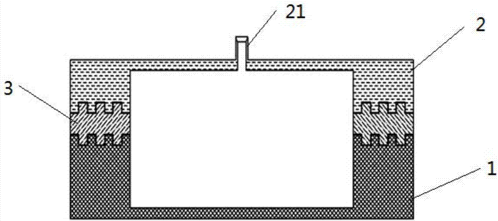
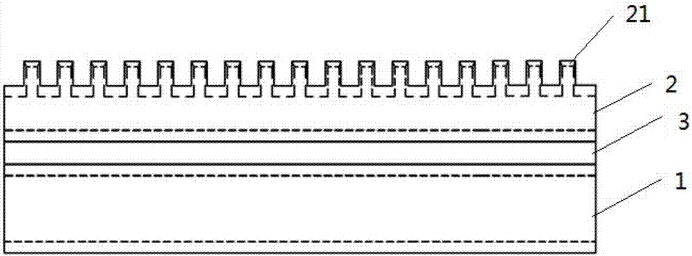
[0023] like Figure 1-Figure 3 As shown, the present embodiment provides a kind of evaporation source, comprising:

[0024] A crucible body 1, the crucible body 1 has an evaporation chamber for accommodating evaporation materials, and one end of the evaporation chamber is open;

[0025] And, buckle the nozzle cover plate 2 on the opening of the evaporation chamber of the crucible body 1, and the nozzle 21 cover is provided with a nozzle 21;

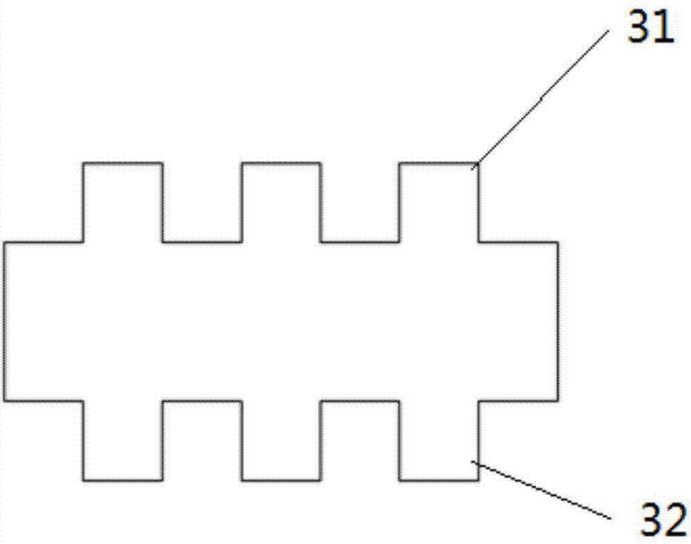
[0026] The crucible body 1 includes a first docking portion for docking with the nozzle cover plate 2; the nozzle cover plate 2 includes a second docking portion for docking with the crucible body 1; the first docking portion A heat insulating layer 3 is provided betw...


PUM


Abstract

The invention relates to an evaporation source. The evaporation source comprises a crucible body and a spray nozzle cover plate, wherein the crucible body is provided with an evaporation chamber used for accommodating a vacuum evaporation material, and one end of the evaporation chamber is open; the spray nozzle cover plate covers the opening of the evaporation chamber of the crucible body, and a spray nozzle is arranged on the spray nozzle cover; the crucible body comprises a first butt-joint part which is in butt joint with the spray nozzle cover plate; the spray nozzle cover plate comprises a second butt-joint part which is in butt joint with the crucible body; and a heat insulation layer is arranged between the first butt-joint part and the second butt-joint part. The invention further relates to a vacuum evaporation system. The evaporation source has the beneficial effects that: the heat insulation layer is arranged for avoiding heat conduction between the crucible body and the spray nozzle cover plate, so that temperature difference between the crucible body and the spray nozzle cover plate is increased, and the problem of blocking holes by materials is improved.

Description

technical field [0001] The invention relates to the technical field of display product production, in particular to an evaporation source and an evaporation system. Background technique [0002] Organic Light-Emitting Diode (OLED) devices are light-emitting devices composed of multiple functional layer stacks. At present, the main manufacturing process of OLED devices is vacuum thermal evaporation technology, that is, the crucible body containing the evaporation materials is heated , the evaporation material is heated and evaporated, and then sprayed onto the surface of the substrate through the nozzle. Since the nozzle is arranged on the nozzle cover plate that is buckled and covered on the crucible body, the evaporation chamber in the crucible body has a certain height, so that the temperature at the nozzle is relatively low, and it is easy to cause material to block the hole wall. The commonly used solution is to heat the nozzle cover at a temperature higher than that of...

Claims


Application Information

Patent Timeline
IPC IPC(8): C23C14/24
CPCC23C14/243
Inventor 胡长奇苏志玮
Owner BOE TECH GRP CO LTD
Why Eureka
Try Eureka