Interference noise reduction device on top of sound barrier

A sound barrier and noise reduction technology, applied in noise absorption devices, buildings, etc., can solve the problems of reduced application safety, height restrictions of sound barriers, and increased engineering costs, and achieves easy processing and installation, widening the frequency range, and good performance. The effect of the noise reduction effect

Pending Publication Date: 2017-11-28
SUZHOU UNIV
View PDF7 Cites 2 Cited by
  • Summary
  • Abstract
  • Description
  • Claims
  • Application Information

AI Technical Summary

Problems solved by technology

[0003] There are following problems and deficiencies in the application of sound barriers at present: 1. The wheel-rail noise produced by trains is repeatedly reflected between the relative sound barrier screen body and the side of the train, forming a concentrated sound source on the sound barrier top, and the concentrated sound source on the top can be Bypassing the top of the sound barrier greatly reduces the noise reduction effect of the sound barrier; 2. The height of the sound barrier is limited, and it is difficult to control the diffracted sound from the top of the sound barrier, and the top of the sound barrier becomes a secondary noise source; 3. With the sound The increase in the height of the barrier not only blocks the line of sight, but also greatly increases the engineering cost and greatly reduces the application safety; 4. The traditional upright sound barrier cannot effectively control the diffracted sound at the top of the sound barrier, and its insertion at certain frequencies trough in losses

Method used


Image

  • Interference noise reduction device on top of sound barrier
  • Interference noise reduction device on top of sound barrier
  • Interference noise reduction device on top of sound barrier

Examples


Embodiment 1

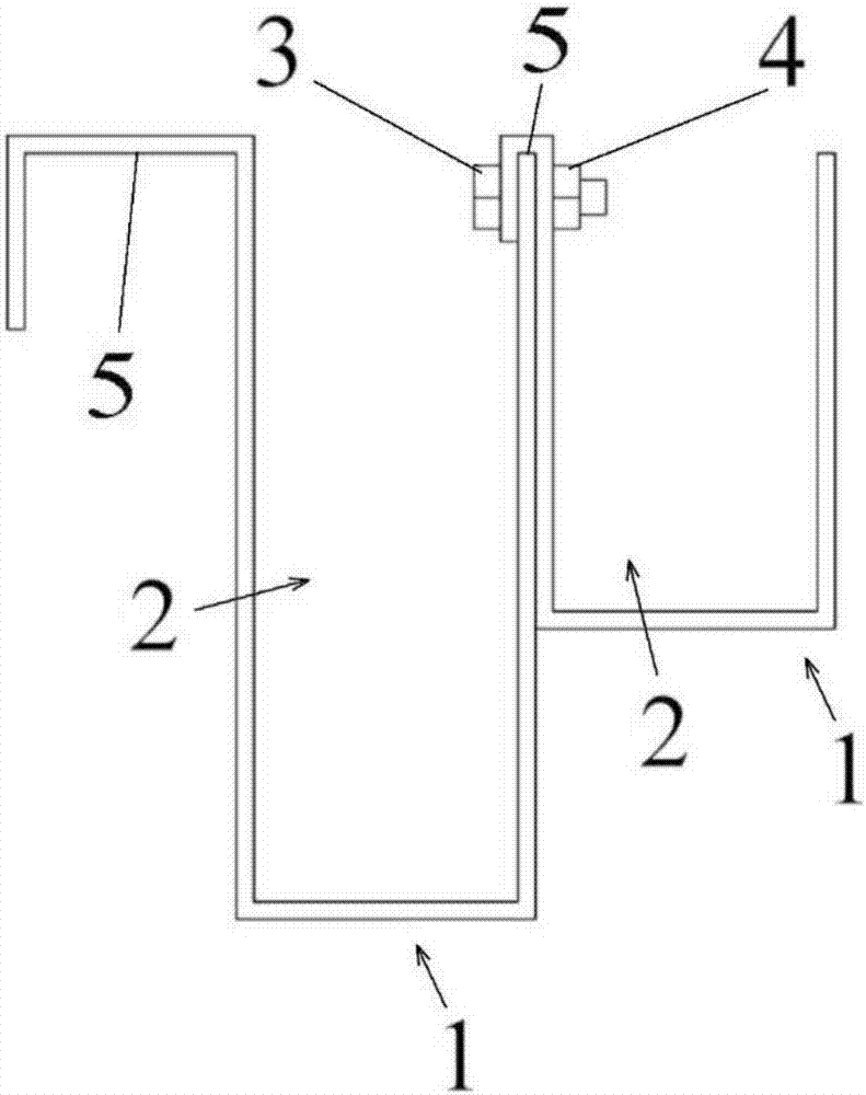
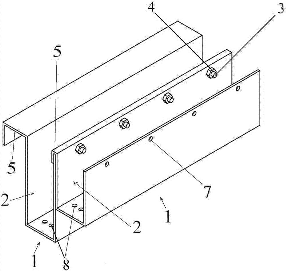
[0024] Reference attached figure 1 And figure 2 The interference noise reduction device on the top of the sound barrier in this embodiment is connected to the top of the sound barrier and includes at least two sound wave reflecting parts 1 with U-shaped sound cavities 2 connected to each other, and the U-shaped sound wave reflecting parts 1 The depth of the acoustic cavity 2 is different.

[0025] In this embodiment, the acoustic wave reflection part 1 is made of aluminum alloy. The cross section of the acoustic wave reflection part 1 is U-shaped.

[0026] In a more preferred embodiment, in a direction from back to front, the depth of the U-shaped acoustic cavity of each acoustic wave reflecting part is sequentially reduced. The forward and backward directions described in this embodiment are defined as: the direction of the sound wave reflecting part toward the sound barrier is rear, and the direction of the sound wave reflecting part away from the sound barrier is forward.

[00...

Embodiment 2

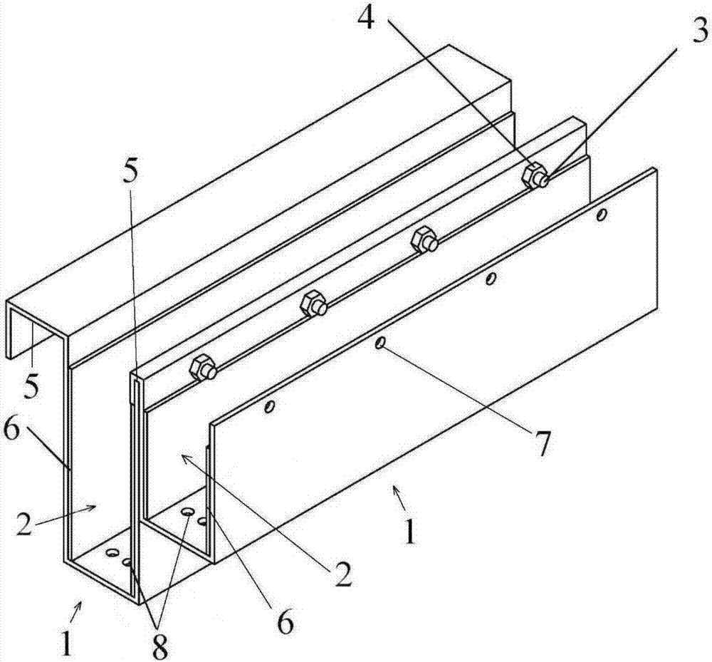
[0032] Reference attached image 3 The difference between the interference noise reduction device on the top of the sound barrier in this embodiment and the first embodiment is only that: the inner wall of each U-shaped acoustic cavity 2 is provided with a sound absorbing material 6. The sound-absorbing material 6 in this embodiment uses sound-absorbing cotton. Preferably, the sound-absorbing material 6 is attached to the front and rear inner walls of the U-shaped acoustic cavity 2.

Embodiment 3

[0034] Reference attached Figure 4 The difference between the interference noise reduction device on the top of the sound barrier in this embodiment and the second embodiment is only that: there are three sound wave reflection parts 1, among which the deep sound wave reflection part 1 of the U-shaped sound cavity 2 is suspended in its own suspension groove 5 On the top of the sound barrier, the U-shaped acoustic cavity 2 has a middle-depth acoustic wave reflecting part 1 suspended by its own suspension groove 5 on the top of the front side wall of the deeper acoustic wave reflecting part 1 of the U-shaped acoustic cavity 2 and the shallow sound wave of the U-shaped acoustic cavity 2 The reflection part 1 is suspended on the top of the front side wall of the sound wave reflection part 1 with the middle depth of the U-shaped acoustic cavity 2 through its own suspension groove 5. The two adjacent sound wave reflecting parts 1 are further fastened by a bolt fastening structure.


PUM


Abstract

The invention discloses an interference noise reduction device on the top of a sound barrier. The interference noise reduction device on the top o the sound barrier is connected to the top of the sound barrier, and comprises at least two sound wave reflection parts with U-shaped sound chambers, wherein the sound wave reflection parts are connected with one another; and the U-shaped sound chambers of the sound wave reflection parts have different depths. According to the interference noise reduction device on the top of the sound barrier, multiple sound wave reflection parts with the U-shaped sound chambers of different depths are assembled, one part of sound waves are reflected at the bottoms of the U-shaped sound chambers of different depths after entering the device, and the sound waves are superposed and offset with sound waves outside the device by increasing the sonic path distance of incident sound waves, and the noise-reducing and silencing aims are achieved. Compared with the prior art, the interference noise reduction device disclosed by the invention is simple in structure and easy to process and mount, the assembling style can be adjusted according to the construction environment, and the device is attractive after construction and has excellent weather resistance. The interference noise reduction device disclosed by the invention has wide frequency range, has an excellent effect of processing diffraction sound waves on the top of the sound barrier and also has an excellent noise reduction effect on medium/low-frequency noise.

Description

Technical field [0001] The invention relates to an interference noise reduction device on the top of a sound barrier, in particular to an interference noise reduction device on the top of a sound barrier for urban rail transit. Background technique [0002] While urban rail transit provides people with a convenient, fast, comfortable, safe, clean and energy-saving travel mode, the noise it generates has a certain impact on the lives of surrounding residents, and the construction of sound barriers is an effective treatment measure. [0003] The current application of sound barriers has the following problems and deficiencies: 1. The wheel-rail noise generated by the train is reflected multiple times between the opposite sound barrier screen and the side of the train, forming a concentrated sound source on the upper part of the sound barrier, and the upper concentrated sound source can be Bypassing the top of the sound barrier, the noise reduction effect of the sound barrier is great...

Claims


Application Information

Patent Timeline
Patent Type & Authority Applications(China)
IPC IPC(8): E01F8/00
CPCE01F8/0094
Inventor 吴兵陈铭
Owner SUZHOU UNIV
Why Eureka
Try Eureka