Underpinning structure and construction method for replacing unqualified shearing wall concrete

A shear wall and concrete technology, applied in the direction of walls, building components, building structures, etc., can solve the problems of common people's disputes, easy to leave traces, etc., and achieve the effect of saving construction period and project cost

Pending Publication Date: 2017-11-28
天津联鉴建筑质量鉴定检测有限公司 +1
0 Cites 12 Cited by

AI-Extracted Technical Summary

Problems solved by technology

Ordinary reinforcements, including carbon fiber and bonded steel, are easy to leave traces, and the subsequent decoration of ordinary pe...

Abstract

An underpinning structure for replacing unqualified shear wall concrete, which includes several columns, upper beams, lower beams, and supports; The upper floor is connected to the upper beam, and the lower beam is supported by the lower beam; the upper beam passes through the hole cut in the shear wall of the previous floor; the lower beam passes through the hole cut in the shear wall of the next floor The hole out; the support is installed under the lower beam to support the lower beam; the entire underpinning structure is used to support the weight of all structures above the replacement floor. Construction methods include: site survey, unloading, erecting underpinning structures, chiseling concrete, supporting formwork, pouring concrete, construction quality inspection, etc. The invention replaces partially unqualified concrete shear walls without dismantling all structures above the unqualified requirements; and the replaced structural form is the same as the original structural form, which greatly saves construction period and engineering cost.

Application Domain

WallsBuilding repairs

Technology Topic

EngineeringShear wall +5

Image

  • Underpinning structure and construction method for replacing unqualified shearing wall concrete
  • Underpinning structure and construction method for replacing unqualified shearing wall concrete
  • Underpinning structure and construction method for replacing unqualified shearing wall concrete

Examples

  • Experimental program(1)

Example Embodiment

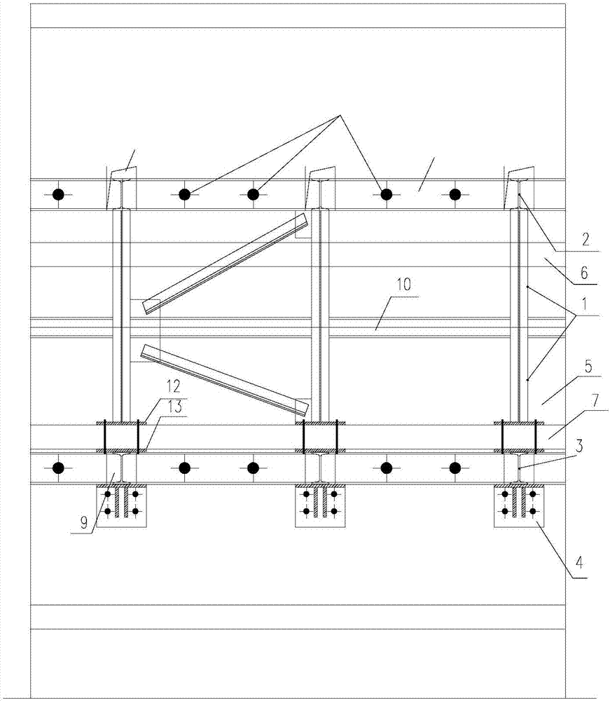
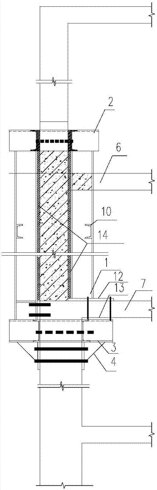
[0030] Example: such as Figure 1 to Figure 4-2 As shown, an underpinning structure for replacing unqualified shear wall concrete includes a number of columns 1, upper beam 2, lower beam 3, and supports 4; the column 1 is installed in the replacement layer of the shear wall where concrete needs to be replaced On both sides of 5, the upper part of the column 1 passes through the upper floor 6 to connect with the upper beam 2, and the lower part is supported by the lower beam 3 under the lower floor 7; the upper beam 2 passes through the shear wall of the upper floor and is cut out The hole 8; the lower beam passes through the hole 9 cut in the shear wall of the next floor; the support 4 is installed under the lower beam 3 to support the lower beam 3; the entire underpinning structure is used to support the replacement layer above The weight of all the structures.
[0031] An upper beam 2, a lower beam 3 and a support 4 are respectively provided above and below the plurality of uprights 1.
[0032] The middle part of the column 1 on the same side of the shear wall that needs to replace concrete, and the shear walls on both sides of the upper beam 2 and the lower beam 3 are provided with reinforced beams 10; the shear force on both sides of the upper beam 2, the lower beam 3 The reinforced beam 10 provided on the wall is fixed by anchor bolts 11.
[0033] The lower end of the column is connected to an upper fixing plate 12, which is placed on the upper surface of the lower floor slab 7, and the upper fixing plate 12 is fixedly connected to the lower fixing plate 13 on the lower surface of the lower floor slab by bolts passing through the lower floor slab 7.
[0034] The column 1 passes through the hole 16 drilled in the upper floor 6, and is restricted and fixed by a limit plate 15, and the limit plate 15 is fixed on the upper floor 16.
[0035] After the lower beam 3 passes through the shear wall of the next floor, both ends are supported by supports 4, and the supports 4 on both sides are fixed to the shear wall of the next floor by bolts.
[0036] A shear wall formwork 14 is provided on the inner side of the column 1 to be removed from the concrete of the shear wall.
[0037] Such as Figure 5 As shown, the distance between the columns 1 arranged according to the length of the wall section is not greater than 900 mm.
[0038] The column 1, the upper beam 2, the lower beam 3, the support 4, the upper fixing plate 12 and the lower fixing plate 13 are all steel components, which are connected by anchor bolts and the like to form a steel structure system.
[0039] The column 1 is I16 steel, the upper beam 3 and the lower beam 4 are I12 steel, and the reinforcing beam 10 is channel steel.

PUM

no PUM

Description & Claims & Application Information

We can also present the details of the Description, Claims and Application information to help users get a comprehensive understanding of the technical details of the patent, such as background art, summary of invention, brief description of drawings, description of embodiments, and other original content. On the other hand, users can also determine the specific scope of protection of the technology through the list of claims; as well as understand the changes in the life cycle of the technology with the presentation of the patent timeline. Login to view more.
Why Eureka
Try Eureka