Angle iron tower climbing device

A technology of angle steel tower and angle steel, which is applied in the field of angle steel tower climbing devices, can solve the problems of poor climbing safety, large torque, rotation of foot nails, etc., and achieve the effect of convenient mounting of seat belts, easy transformation and reliable connection

Pending Publication Date: 2017-11-28
GUIZHOU POWER GRID CO LTD
View PDF8 Cites 0 Cited by
  • Summary
  • Abstract
  • Description
  • Claims
  • Application Information

AI Technical Summary

Problems solved by technology

[0002] One end of the single tendon foot nails used on the existing angle steel tower is fixedly connected to the steel pipe or the angle steel tower through a nut, and they are arranged in a staggered manner. Serious injury, and the nut may be loose due to the long-term erosion of the sun and rain under stress, and the climbing safety is poor; in addition, a safety belt is installed on the lower side of the outer end of the existing single tendon foot nail The hook frame will be frozen and closed in case of ice and snow disasters. If a large square frame is used, when the foot nails are held by hand during the climbing process, the torque will become larger and the foot nails will rotate.

Method used


Image

  • Angle iron tower climbing device
  • Angle iron tower climbing device

Examples


Embodiment 1

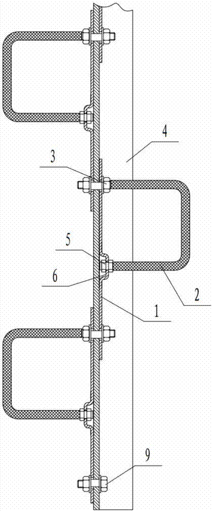
[0022] Embodiment 1: as Figure 1-Figure 2 Shown, a kind of angle steel tower climbing device comprises connecting plate 1 and U-shaped foot nail 2, and the upper and lower ends of connecting plate 1 are fixedly connected to On the angle steel 4 of the angle steel tower, the short-distance wire ends of the U-shaped foot nails 2 are fixedly connected to the connecting plate 1, and the two ends of the U-shaped foot nails 2 are vertically arranged, and a plurality of U-shaped foot nails 2 are arranged along the direction of the angle steel 4. The left and right crossing arrangement, the connection plate 1 is arranged in multiple pieces, and the connection plate 1 is set in a circular arc structure, and the acute angle is blunt.

[0023] Preferably, the above-mentioned two adjacent U-shaped foot nails 2 located on the left and right sides of the angle steel on which the angle steel 4 is installed are separated by 45-50 cm.

[0024] Preferably, the long-distance wire ends of the a...

Embodiment 2

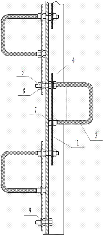
[0029] Embodiment 2: the connecting plate 1 and the U-shaped foot nail 2 can also be used as figure 2 In the connection shown in this way, the short-distance wire ends of the above-mentioned U-shaped foot nails 2 are fixedly connected to the connecting plate 1. One end passes through the connecting plate 1 and is fixedly connected to the connecting plate 1 by double lock nuts 27. The connecting plate 1 The two ends are suspended in the air by two padding nuts 8, and the two padding nuts 8 are sleeved on the long-distance wire ends of the U-shaped foot nails 2 and pass through one end of the angle steel 4 using the original foot nail holes on the angle steel 4.


PUM


Abstract

The invention discloses an angle iron tower climbing device. The angle iron tower climbing device comprises connecting plates and U-shaped foot pins; the upper end and the lower end of each connecting plate are penetrated by long screw pitch ends of two corresponding U-shaped foot pins, and the long screw pitch ends of the U-shaped foot pins are fixedly connected with an angle iron of an angle iron tower; short screw pitch ends of the U-shaped foot pins are fixedly connected with the connecting plates; the U-shaped foot pins are vertically arranged on the two sides of the angle iron in two lines in a left-right alternative manner along the direction of the angle iron; and the plurality of connecting plates are arranged in an alternative manner. According to the angle iron tower climbing device, the U-shaped foot pins and the limit connecting plates are arranged on a steel support conveniently and rapidly using original foot pin holes of single-rib foot pins left on the steel support, assembling and disassembling and maintenance are convenient, impact of operating personnel with end parts of single-rib foot pins after falling is avoided, operating dangerousness is reduced, accident seriousness is reduced, double end fixed connection is adopted, foot pin connection is reliable, climbing is more safe, hanging of safety belts is more convenient, and it is convenient to find slits via cleaning for hanging of safety belts even in winter when iron towers are covered with ice.

Description

technical field [0001] The invention relates to a climbing device for an angle steel tower, which belongs to the technical field of electric power maintenance climbing equipment. Background technique [0002] One end of the single tendon foot nails used on the existing angle steel towers is fixedly connected to the steel pipe or the angle steel tower through nuts, and they are arranged in a staggered manner. Serious injury, and the nut may be loose due to the long-term erosion of the sun and rain under stress, and the climbing safety is poor; in addition, a safety belt is installed on the lower side of the outer end of the existing single tendon foot nail The hook frame will be frozen and closed in case of ice and snow disasters. If a large square frame is used, when the foot nails are held by hand during climbing, the torque will become larger and the foot nails will rotate. Part of the seat belt hook frame is welded, and the anti-corrosion and anti-shedding of the welding...

Claims


Application Information

Patent Timeline
Patent Type & Authority Applications(China)
IPC IPC(8): E06C9/04
CPCE06C9/04
Inventor 杨杰
Owner GUIZHOU POWER GRID CO LTD
Why Eureka
Try Eureka