Laser beam joining method and laser machining optics

A technology for laser processing and optical instruments, applied in the field of laser processing optical instruments, can solve problems such as increasing the scope, and achieve the effect of improving energy balance and increasing light intensity

Inactive Publication Date: 2017-11-28
SCANSONIC MI
View PDF23 Cites 8 Cited by
  • Summary
  • Abstract
  • Description
  • Claims
  • Application Information

AI Technical Summary

Problems solved by technology

An increase in the overall energy input in the workpiece close to the joint can only be achieved by extending the laser spot line, but the range of energy input also increases with the reduction of the energy density

Method used


Image

  • Laser beam joining method and laser machining optics
  • Laser beam joining method and laser machining optics
  • Laser beam joining method and laser machining optics

Examples


Embodiment Construction

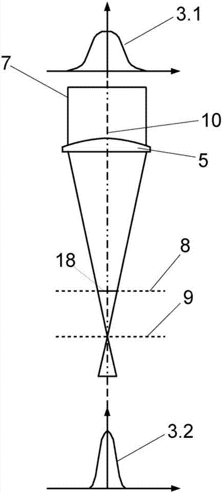
[0060]FIG. 1 shows the beam path of a laser beam 7 in a laser processing optics according to the prior art. The laser beam 7 with a Gaussian radiation intensity distribution 3.1 in cross-section is focused by the focusing device 5 onto the laser focal plane 9, whereby a (out-of-focus) laser focal spot 18 is formed in the processing plane 8, in which The cross-section contains the radiation intensity distribution 3.2. The two Gaussian radiation intensity distributions 3.1 and 3.2 each have a maximum on the beam axis 10 .

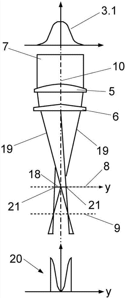
[0061] figure 2 The beam path of the laser beam 7 according to the invention is shown. A laser beam 7 with a radiation intensity distribution 3.1 in cross-section is focused by a focusing device 5 onto the laser focal plane 9 and split into two partial beams 19 by a beam splitter 6 here of the top plate type and deflected in this way , ie a coherent laser focal spot 18 is formed in the processing plane 8 by the two partial beams 19 . In this case, the di...


PUM


Abstract

The invention relates to a method for joining workpieces (12, 13) using a laser beam (7), wherein the laser beam (7) is focused onto a focal plane downstream of the machining plane in the beam propagation direction and subdivided into a plurality of partial beams (19) by means of a beam dividing device (6). The subdivision is effected in a geometric manner, i.e. the partial beam cross sections emerge from a division of the geometric form of the beam cross section of the laser beam (7). The partial beams (19) are guided onto the machining plane (8) in a crossed manner and with an offset from one another in such a way that an extended laser focus (18) is formed. The radiation intensity distribution of the superposed partial beams (19) in the machining plane (8) along a line perpendicular to the seam joint respectively has a maximum at the end regions thereof. As a result thereof and as a result of the spatially extended region of high radiation intensity on both sides along the seam joint compared to the prior art, there is, firstly, an improvement in the edge connection and hence in the quality of the seam joint and, secondly, an increase in the process efficiency.

Description

technical field [0001] The invention relates to a method for welding or brazing workpieces by means of a laser beam and to an optical device for laser processing. In this way, in addition to a better edge connection of the welded or soldered seam and thus a higher seam quality, a higher process efficiency can also be achieved. Background technique [0002] Laser welding and laser brazing are known for joining two workpieces by means of a laser beam. In both cases, the workpieces at the joint are joined to each other by melting the material. During laser welding, the workpiece or its surface melts; during laser brazing, only the welding wire applied to or introduced into the joint melts. [0003] Conversely, laser welding can also be carried out using welding wire, for example in the case of joints with large gap widths. The welding wire is positioned on or in the slit of the joint; so that the laser beam melts the edges of the two workpieces and the welding wire at the jo...

Claims


Application Information

Patent Timeline
Patent Type & Authority Applications(China)
IPC IPC(8): B23K1/005B23K26/06B23K26/067B23K26/073
CPCB23K1/0056B23K26/0608B23K26/067B23K26/073B23K26/0643B23K26/0648B23K26/0676
Inventor 斯特芬·瓦尔特
Owner SCANSONIC MI
Why Eureka
Try Eureka