Image-reading apparatus and image-reading method
An image reading device and image data technology, which are applied in image communication, image data processing, image data processing and other directions, can solve the problem of unable to reproduce the accurate image of the lost data position, etc., and achieve the effect of eliminating deformation
- Summary
- Abstract
- Description
- Claims
- Application Information
AI Technical Summary
Problems solved by technology
Method used
Image
Examples
Embodiment approach 1
[0035] "1-1" Structure of Embodiment 1
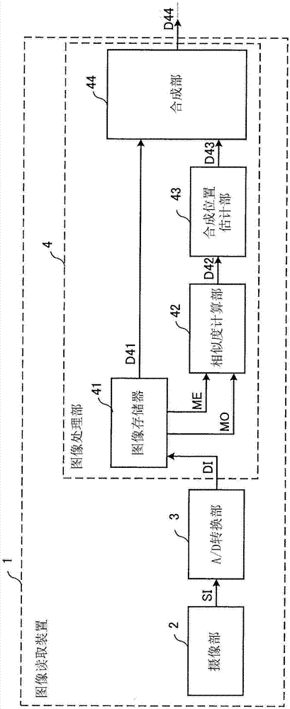
[0036] figure 1 It is a functional block diagram showing a schematic configuration of the image reading device 1 according to Embodiment 1 of the present invention. like figure 1 As shown, the image reading device 1 has an imaging unit 2 , an A / D (analog / digital) conversion unit 3 , and an image processing unit 4 . Furthermore, the image processing unit 4 has an image memory 41 , a similarity calculation unit 42 , a combined position estimation unit 43 , and a combined unit 44 . In addition, the image reading device 1 may include a transport unit for transporting a document and a control unit for controlling the entire device. The conveyance unit and the processor as the control unit will be described in Embodiment 2 described later.
[0037]The imaging unit 2 has N (N is an integer greater than or equal to 2) sensor chips arranged linearly on the substrate. Each of the N sensor chips has a plurality of imaging elements arranged ...
Embodiment approach 2
[0105] Part of the functions of the image reading device 1 in Embodiment 1 described above and Embodiment 3 described later may also be implemented by a hardware configuration, or may be implemented by a microprocessor including a CPU (Central Processing Unit: Central Processing Unit). executed by a computer program. When a part of the functions of the image reading device 1 is realized by a computer program, the microprocessor downloads and executes the computer program from a computer-readable storage medium, whereby part of the functions of the image reading device 1 can be realized.
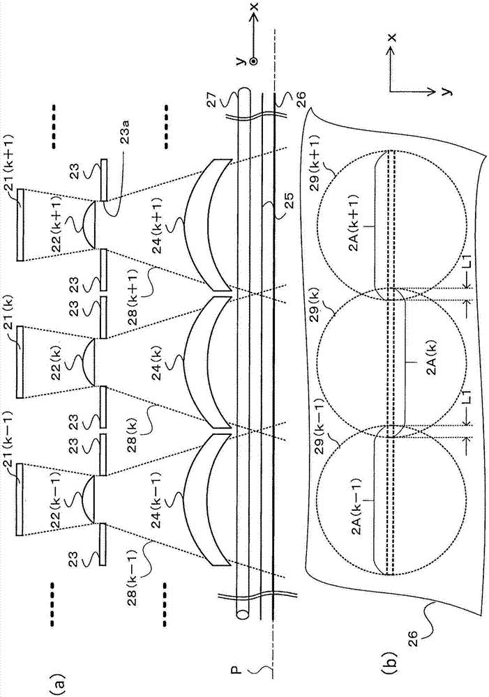
[0106] Figure 14 It is a block diagram showing a hardware configuration capable of realizing part of the functions of the image reading device by a computer program. like Figure 14 As shown, the image reading device 1a has an imaging unit 2, an A / D conversion unit 3, and an arithmetic unit 5. In the y-axis direction ( figure 2 (a) and (b) show) conveying section 6 that conveys the docum...
Embodiment approach 3
[0112] The image reading device 1 described in Embodiment 1 is configured as follows: Figure 17The combination magnification setting unit 45 in the combination unit 44 of the image processing unit 4 configured as shown calculates the reading width Wc in the main scanning direction of the reading area (the main scanning width Wc between the positions at both ends) based on the position data D43 at both ends of each unit. The width in the scanning direction) is used to set the combination magnification and combination position based on the width Wr between the reading width Wc and the combination reference position Pr. However, it can also be configured to use Figure 18 The composite magnification setting unit 45b shown calculates the overlap amount at the time of reading based on the position data D43, and sets the composite magnification and the composite Location.
[0113] "3-1" Structure of Embodiment 3
[0114] Figure 18 It is shown that in the image processing unit ...
PUM
 Abstract
Description
Claims
Application Information
 - R&D
- Intellectual Property
- Life Sciences
- Materials
- Tech Scout
- Unparalleled Data Quality
- Higher Quality Content
- 60% Fewer Hallucinations
Browse by: Latest US Patents, China's latest patents, Technical Efficacy Thesaurus, Application Domain, Technology Topic, Popular Technical Reports.
© 2025 PatSnap. All rights reserved.Legal|Privacy policy|Modern Slavery Act Transparency Statement|Sitemap|About US| Contact US: help@patsnap.com


