Horizontal stretchable type protection cover of large machining center machine tool

A machining center and horizontal telescopic technology, applied in the field of protective covers, can solve the problems of inconvenient chip removal and chip collection, large space occupation, etc., and achieve the effects of automatic collection, easy operation, and simplified structure

Active Publication Date: 2017-12-01
NINGXIA KOCEL MACHINE TOOL ACCESSORIES
View PDF11 Cites 2 Cited by
  • Summary
  • Abstract
  • Description
  • Claims
  • Application Information

AI Technical Summary

Problems solved by technology

The above structures all adopt a fully enclosed structure, which takes up a lot of space and is not convenient for chip removal and collection

Method used


Image

  • Horizontal stretchable type protection cover of large machining center machine tool
  • Horizontal stretchable type protection cover of large machining center machine tool
  • Horizontal stretchable type protection cover of large machining center machine tool

Examples


Embodiment 1

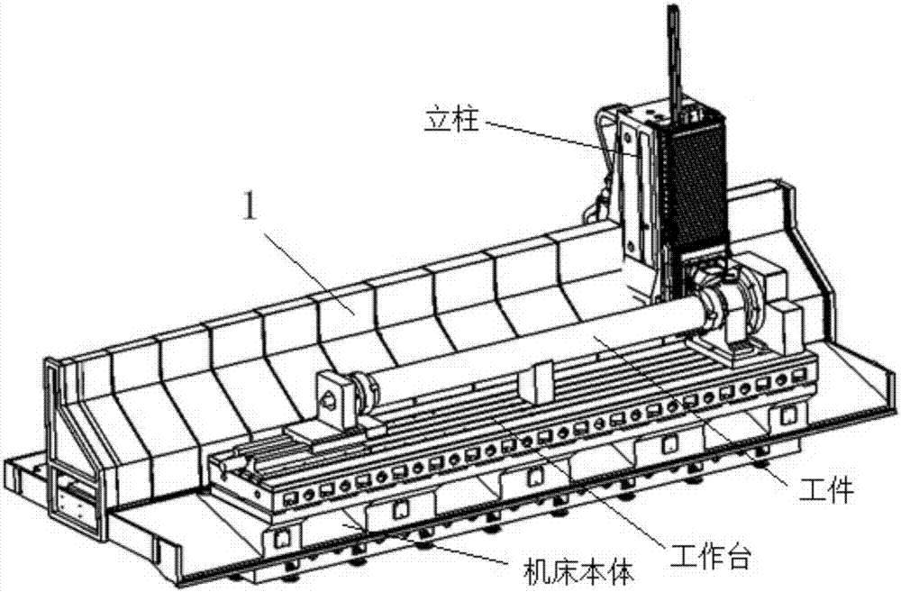
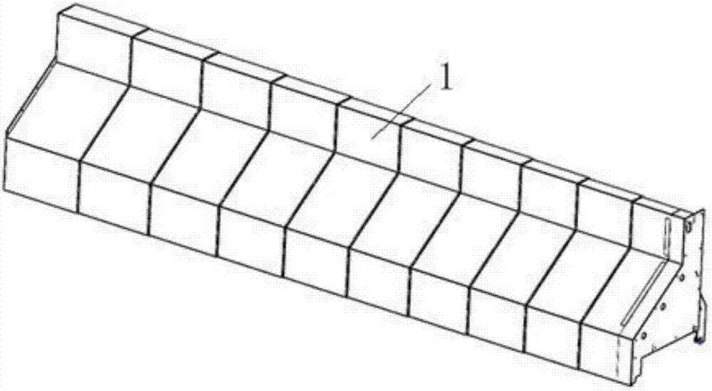
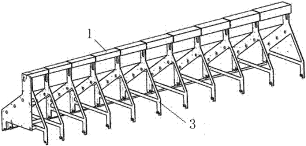
[0022] Such as figure 1 with Figure 5 As shown, a horizontal telescopic protective cover for a large-scale machining center machine tool includes a plurality of cover bodies 1 that are sleeved together. The cover body 1 is a semi-closed structure and is mainly composed of a cover panel 2, a vertical plate 3 and a transition The connecting plate 4 is formed, the cover panel 2 is fixed on the vertical plate 3 through the transition connecting plate 4, and the cover panel 2 has a Z-shaped structure, and the vertical plate 3 has a convex structure.

[0023] Among them, the vertical plate 3 is mainly composed of a triangular plate 5, a vertical top plate 6 and a leg plate 7. The triangular plate 5 is a hollow structure, the top of the triangular plate 5 is provided with a vertical top plate 6, and the bottom of the triangular plate 5 is provided on both sides There are leg plates7. The cover panel 2 is mainly composed of a vertical plate 8, a sloping plate 9, a horizontal plate 10 an...

Embodiment 2

[0026] The transition connecting plate 4 is arranged close to the inner wall of the cover panel 2, the two ends of the transition connecting plate 3 are provided with insertion notches 12, and the transition connecting plate 3 and the cover panel 2 are connected by inserting and rivets. The other structure is the same as the first embodiment. The cover panel is designed with an L-shaped plate so that the edge of the contact area between the cover panel and the transition connecting plate 3 forms a plug-in boss. The connecting area between the transitional connecting plate 4 and the cover panel is designed with an inserting gap to form an inserting process. After the insertion is completed, the vertical plate and the transition connecting plate are fastened together by rivets to ensure the manufacturing accuracy of each section of the shield. After all connections are completed, electric welding reinforcement is performed at the designated position.

Embodiment 3

[0028] A plurality of supporting roller assemblies 13 are arranged between the cover bodies 1 that are sleeved together. The supporting roller assembly 13 is mainly composed of a fixed block 14, a fixed plate 15, a roller frame 16 and a roller 17, and the fixed block 14 is fixed on the transition plate 4, the fixed plate 15 is fixed on the fixed block 14, the fixed plate 15 is provided with a mounting bayonet 18, the roller frame 16 is provided with a fixed card slot 19, the roller frame 16 is fixed to the fixed plate 15 through the fixed card slot 19 On the mounting bayonet 18, the roller 17 is mounted on the roller frame 16. Others are the same as the first embodiment.

[0029] The supporting roller is clamped on the roller bracket through its own slot, and the roller bracket is connected with the shield vertical plate by screws. Structural size requirements: The cut surface of the roller is 0.4~1.0mm higher than the vertical plate, and the specific height depends on the size ...


PUM


Abstract

The invention relates to a horizontal stretchable type protection cover of a large machining center machine tool, belongs to a protection cover, and is particularly suitable for protection on a large-stroke large-span machining center machine tool or a gantry machining center machine tool guide rail and lead screw and other components. The protection cover is formed by a plurality of cover bodies connected together in a sleeved manner, the cover bodies are of semi-closed structures, each cover body is mainly formed by a cover panel, a vertical plate and a transition connecting plate, each cover panel is fixed to the corresponding vertical plate through the corresponding transition connecting plate and is of a Z-shaped structure, and each vertical plate is of a convex structure. The protection cover adopts a semi-closed protection structure, the surround zone space of a machine tool body is reasonably used, and advantages of a metal plate structure are sufficiently used.

Description

Technical field [0001] The invention relates to a protective cover, which is especially suitable for the protection of parts such as a large-stroke, large-span machining center machine tool or a gantry machining center machine tool guide rail and a lead screw. Background technique [0002] At present, large-scale machining center machine tools are mainly used for the processing of large-scale rotary parts such as milling, drilling, boring, expanding, and reaming. The machine tool has a long protection area and difficult protection. The existing common telescopic steel plate protective cover type is mainly a "U"-shaped structure or a "mountain" structure, installed horizontally, and is the most widely used protective cover. For example, the patent number is 201410762869.X, the patent name is a floor-standing boring and milling machine column guide rail guard, and the patent number is 201620171689.9, and the patent name is a machine tool with a double-layer guide rail guard. "Type...

Claims


Application Information

Patent Timeline
Patent Type & Authority Applications(China)
IPC IPC(8): B23Q11/08
CPCB23Q11/0825
Inventor 孙俊渊原晓雷杨冰马亚文丁强王彦涛赵敬
Owner NINGXIA KOCEL MACHINE TOOL ACCESSORIES
Why Eureka
Try Eureka