System and method for controlling temperature of hydraulic oil

A hydraulic system and hydraulic oil technology, which is applied in the field of hydraulic oil temperature control system, can solve the problem of single control mode, achieve good cooling effect and improve precision

Active Publication Date: 2017-12-01
WUHAN MARINE MACHINERY PLANT
View PDF9 Cites 15 Cited by
  • Summary
  • Abstract
  • Description
  • Claims
  • Application Information

AI Technical Summary

Problems solved by technology

[0006] Whether the air cooler works is directly controlled by the controller, and the control method is too simple

Method used


Image

  • System and method for controlling temperature of hydraulic oil
  • System and method for controlling temperature of hydraulic oil
  • System and method for controlling temperature of hydraulic oil

Examples


Embodiment 1

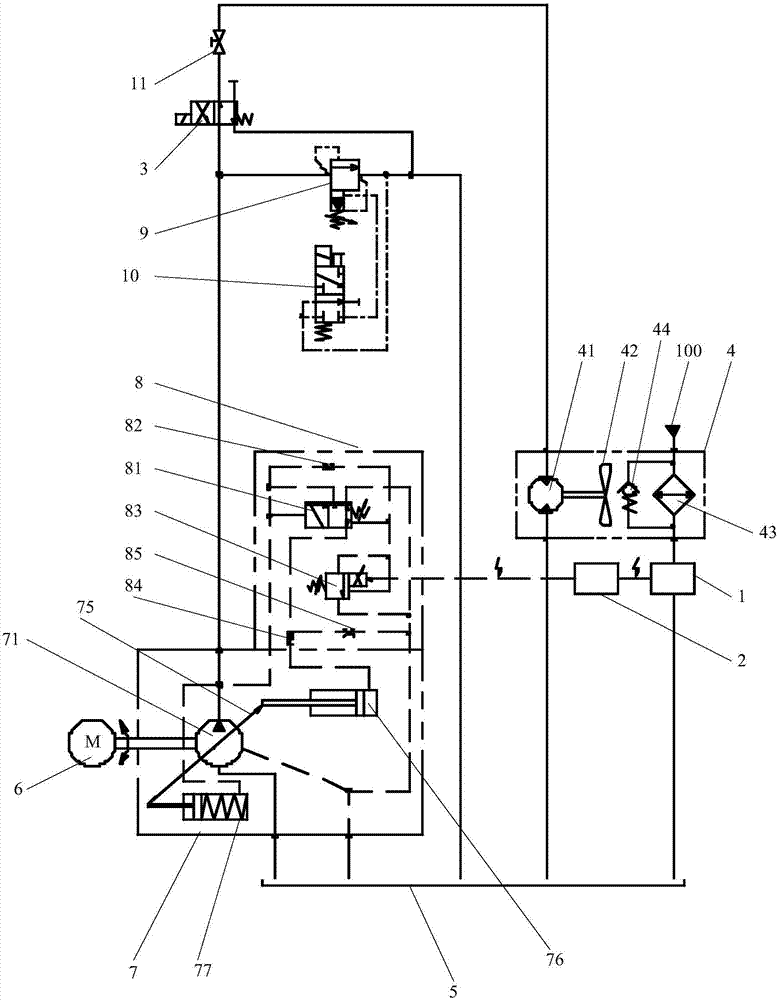
[0034] The embodiment of the present invention provides a system for controlling the temperature of hydraulic oil, see figure 1 , the system includes a temperature sensor 1, a controller 2, a first electromagnetic reversing valve 3, an air cooler 4 and an oil tank 5, the oil tank 5 is used to provide hydraulic oil for the hydraulic system, and the temperature sensor 1 is arranged at the oil outlet of the hydraulic system On the oil path between 100 and the fuel tank 5, the controller 2 is electrically connected to the temperature sensor 1.

[0035] It is easy to know that the hydraulic oil flows in the oil circuit when the oil circuit is turned on, and is stored in the oil circuit when the oil circuit is closed, so there is always hydraulic oil in the oil circuit, and the temperature sensor can detect the temperature of the hydraulic oil at any time .

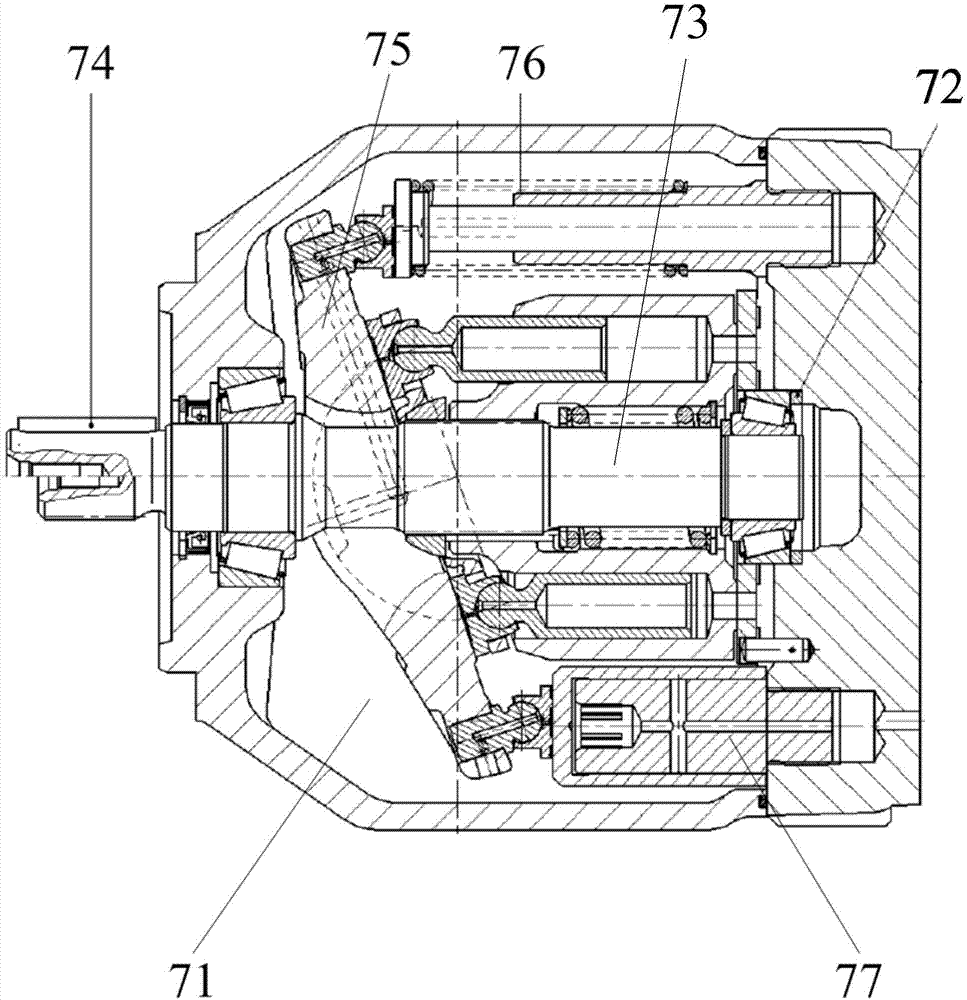
[0036] In this embodiment, the system also includes a motor 6, a variable plunger pump 7, a control valve group 8, and a pil...

Embodiment 2

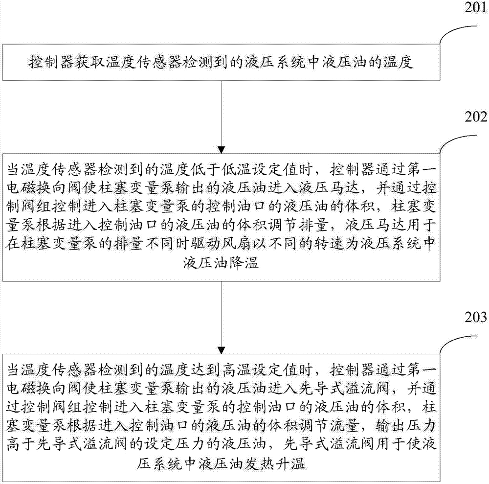
[0070] The embodiment of the present invention provides a method for controlling the temperature of hydraulic oil implemented by the system provided in Embodiment 1, see image 3 , the method includes:

[0071] Step 201: The controller acquires the temperature of the hydraulic oil in the hydraulic system detected by the temperature sensor.

[0072] Step 202: When the temperature detected by the temperature sensor reaches the high temperature setting value, the controller makes the hydraulic oil output by the plunger variable pump enter the hydraulic motor through the first electromagnetic reversing valve, and enters into the plunger variable pump through the control valve group The volume of hydraulic oil in the control oil port, the plunger variable pump adjusts the displacement according to the volume of hydraulic oil entering the control oil port, and the hydraulic motor is used to drive the fan at different speeds for hydraulic pressure when the displacement of the plunger...


PUM


Abstract

The invention discloses a system and method for controlling the temperature of hydraulic oil and belongs to the field of electronic control systems. The system comprises a temperature sensor, a controller, a first electromagnetic directional valve, an air cooler, an oil tank, a motor, a plunger variable pump and a pilot operated compound relief valve. The temperature sensor is arranged between a hydraulic system and the oil tank, and the controller is electrically connected with the temperature sensor. The plunger variable pump is in transmission connection with the motor, an oil inlet of the plunger variable pump communicates with the oil tank, the control end of the plunger variable pump is electrically connected with the controller, and an oil outlet of the plunger variable pump communicates with an oil inlet of the first electromagnetic directional valve and an oil inlet of the pilot operated compound relief valve at the same time. The control end of the first electromagnetic directional valve is electrically connected with the controller, a working oil opening of the first electromagnetic directional valve communicates with an oil inlet of the air cooler, an oil outlet of the air cooler communicates with the oil tank, and an oil outlet of the pilot operated compound relief valve communicates with the oil tank. The system and method for controlling the temperature of the hydraulic oil improve the control precision.

Description

technical field [0001] The invention relates to the field of electric control systems, in particular to a system and method for controlling the temperature of hydraulic oil. Background technique [0002] The normal operation of the hydraulic system requires the temperature and viscosity of the hydraulic oil to be within a certain range. The temperature of the hydraulic oil has a great influence on the viscosity of the hydraulic oil. Therefore, the temperature of the hydraulic oil is usually controlled so that the temperature of the hydraulic oil and The viscosity is right and the hydraulic system is working fine. [0003] The existing hydraulic oil temperature control system includes an oil pump, a two-position two-way solenoid valve, a throttle valve, an air cooler, a controller, a temperature sensor and an oil tank. The oil pump is simultaneously connected with the P port of the two-position two-way solenoid valve and the oil tank. The air cooler is connected with the por...

Claims


Application Information

Patent Timeline
Patent Type & Authority Applications(China)
IPC IPC(8): F15B21/04
CPCF15B21/041F15B21/042
Inventor 汤波吴健任建辉王进峰
Owner WUHAN MARINE MACHINERY PLANT
Why Eureka
Try Eureka