
Modem method for suppressing luminous power fluctuation used for optical fiber current transducer

A technology of current transformer and fiber optic current, applied in the direction of voltage/current isolation, etc., can solve the problems of device parameter fluctuations that are difficult to meet the requirements, the actual effect is not ideal, and the technical difficulty is large, so as to improve the stability of the test and the level of intelligence , Improve the effect of high and low temperature stability

Active Publication Date: 2017-12-01
BEIJING AEROSPACE TIMES OPTICAL ELECTRONICS TECH +1
View PDF9 Cites 4 Cited by
  • Summary
  • Abstract
  • Description
  • Claims
  • Application Information

AI Technical Summary

Problems solved by technology

As far as the current technical level is concerned, the optimization of the optical path is limited by the technical level of the existing domestic optical devices, and the fluctuation of device parameters is difficult to meet the requirements; the modulation of the light intensity of the light source is technically difficult and costly, and the actual effect is not ideal

Method used


Image

  • Modem method for suppressing luminous power fluctuation used for optical fiber current transducer
  • Modem method for suppressing luminous power fluctuation used for optical fiber current transducer
  • Modem method for suppressing luminous power fluctuation used for optical fiber current transducer

Examples


Embodiment Construction

[0036] Below in conjunction with accompanying drawing, the present invention is described in further detail:

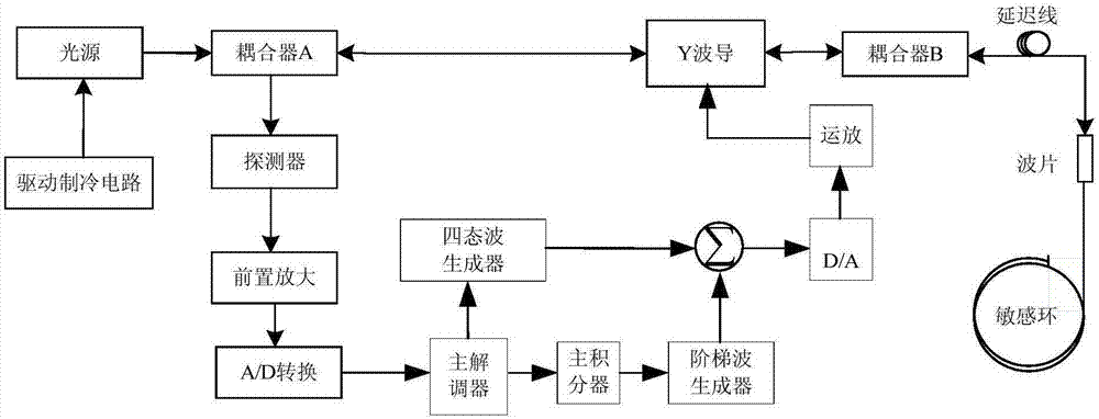
[0037] figure 1 is a schematic diagram of the fiber optic current transformer of the present invention. Such as figure 1 As shown, under the action of the driving refrigeration circuit, the light emitted by the light source enters the integrated optical device through the coupler A, and after the phase modulation of the light by the Y waveguide integrated optical device, two beams of linearly polarized light are output, one of which is received by Modulation, two beams of linearly polarized light pass through the coupler B, enter the delay line along the fast axis and slow axis of the polarization-maintaining fiber respectively, and then pass through the λ / 4 wave plate to convert into two beams of circularly polarized light, one of which is left-handed and the other The beam is right-handed and propagates into the sensitive optical fiber of the fiber ring. Under the...


PUM


Abstract

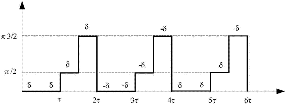
The invention discloses a modem method for suppressing luminous power fluctuation used for an optical fiber current transducer. The method comprises the following steps: switching on an optical fiber current transducer, a data demodulating module generating a modulation waveform, the modulation waveform being a four-state waveform; applying offset of a fixed amplitude on each modulation sequence in the modulation waveform, wherein a waveform corresponding to each four-state modulation cycle is a four-state waveform unit, symbols of offsets applied on the modulation sequences of adjacent four-state waveform units being opposite; after data demodulation on each two adjacent four-state waveform units, a luminous power value and a current value are obtained. The method can effectively reduce influence of luminous power fluctuation on accuracy of tests, stabilizes output, and is beneficial for improving small current measurement precision of an optical fiber current transducer, and has very important effect on improving high and low temperature stability of an optical fiber current transducer.

Description

technical field [0001] The invention belongs to the field of optical fiber current transformers, in particular to a modulation and demodulation method for suppressing optical power fluctuations of optical fiber current transformers. Background technique [0002] As a new type of current measuring equipment, the fiber optic current transformer has the advantages of simple insulation, small size, safety and reliability, digitization, intelligence, and integration of measurement, measurement, and protection. It is the key equipment for the construction of intelligent substations. The research and development of fiber optic current transformers started earlier in foreign countries, and they were also the first to carry out network operation. The research and development of optical fiber current transformers in my country started relatively late, but it has developed rapidly and the technical level has improved greatly. In recent years, especially driven by the demand for intelli...

Claims


Application Information

Patent Timeline
Patent Type & Authority Applications(China)
IPC IPC(8): G01R15/24
CPCG01R15/24
Inventor 张志鑫司磊王利清张峰赵海鹏武永鹏靳俊杰张生营
Owner BEIJING AEROSPACE TIMES OPTICAL ELECTRONICS TECH
Learn More