DC system insulating resistor monitoring circuit, system and method
An insulation resistance and monitoring circuit technology, applied in the field of electric vehicles, can solve the problems of increased DC system ripple, undetectable insulation resistance faults, and reduced equipment insulation performance, etc., to achieve the effect of improving detection accuracy
- Summary
- Abstract
- Description
- Claims
- Application Information
AI Technical Summary
Problems solved by technology
Method used
Image
Examples
Embodiment 1
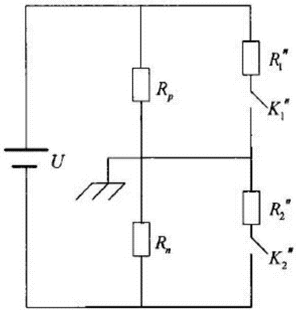
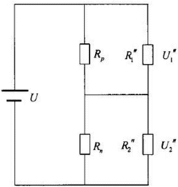
[0061] Firstly, the present invention provides a monitoring circuit for real-time monitoring of the insulation resistance of the DC system of the electric vehicle, so as to calculate the value of the insulation resistance of the DC system. The following specifically introduces the circuit composition of the monitoring circuit of the present invention, please refer to image 3 , which is a circuit diagram of the monitoring circuit of the present invention. The invention provides a DC system insulation resistance monitoring circuit, which includes: a voltage boosting circuit, a monitoring circuit and a voltage value sampling circuit.
[0062] The boost circuit includes a first booster T1 and a second booster T2.
[0063] The monitoring circuit includes a first relay contact S1, a second relay contact S2, a first diode D1, a second diode D2, a first resistor R1, a second resistor R2, a third resistor R3, The fourth resistor R4, the fifth resistor R5, the sixth resistor R6, the ...
Embodiment 2
[0071] In combination with the monitoring circuit of Embodiment 1, the present invention also provides a monitoring system for the insulation resistance of the DC system of the electric vehicle. For details, please refer to Figure 4 , which is a connection block diagram of the monitoring system of the present invention. The present invention also provides a DC system insulation resistance monitoring system, which includes a battery pack device 1 , an insulation monitoring device 2 , an MCU processor 3 , a battery management system 4 and a vehicle controller 5 .
[0072] The insulation monitoring device 2 is used to monitor the insulation resistance of the battery pack device;
[0073] The MCU processor 3 is respectively connected to the battery management system and the insulation monitoring device for receiving instructions from the battery management system, and sending the resistance value of the insulation resistance monitored by the insulation monitoring device to the b...
Embodiment 3
[0084] see Figure 5 , which is a flowchart of the steps of the monitoring method of the present invention. Based on the DC system insulation resistance monitoring system in Embodiment 2, the present invention also provides a monitoring method using the above DC system insulation resistance monitoring system, including the following steps:
[0085] Step S1: Receive the monitoring command, close the relays S1 and S2, the MCU does not give the PWM signal, and the boost circuit does not work;
[0086] Step S2: Sampling the voltages of the third resistor R3 and the fifth resistor R5, and calculating the voltages U+, U- on the insulation resistance of the positive and negative busbars of the DC system to the ground and the total voltage of the DC system U=U++U-, then The voltage division ratio of the total voltage of the DC bus divided by the insulation resistance of the positive and negative bus to the ground is N=U- / U+=Rn / Rp.
[0087] S3: When Rn>Rp, and U, U+ and U- are within...
PUM
 Abstract
Description
Claims
Application Information
 - R&D
- Intellectual Property
- Life Sciences
- Materials
- Tech Scout
- Unparalleled Data Quality
- Higher Quality Content
- 60% Fewer Hallucinations
Browse by: Latest US Patents, China's latest patents, Technical Efficacy Thesaurus, Application Domain, Technology Topic, Popular Technical Reports.
© 2025 PatSnap. All rights reserved.Legal|Privacy policy|Modern Slavery Act Transparency Statement|Sitemap|About US| Contact US: help@patsnap.com


