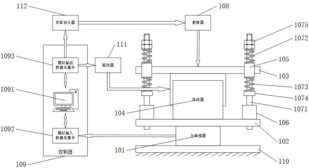
Experimental platform used for verifying vibration isolation effect of active control methods
An experimental platform and active control technology, applied in the direction of electrical testing/monitoring, etc., can solve problems such as inapplicable vibration isolation effects of different algorithms, comparison of inapplicable effects, complex mechanical structures, etc., to achieve algorithm verification and evaluation, simple structure , the effect of high linearity
- Summary
- Abstract
- Description
- Claims
- Application Information
AI Technical Summary
Problems solved by technology
Method used
Image

Examples
Embodiment Construction
[0030] The following will clearly and completely describe the technical solutions in the embodiments of the present invention with reference to the accompanying drawings in the embodiments of the present invention. Obviously, the described embodiments are only some, not all, embodiments of the present invention. Based on the embodiments of the present invention, all other embodiments obtained by persons of ordinary skill in the art without making creative efforts belong to the protection scope of the present invention.
[0031] The purpose of the present invention is to provide an experimental platform for verifying the vibration isolation effect of the active control method, which can carry out experimental verification of the vibration isolation effect of different active control algorithms.
[0032] In order to make the above objects, features and advantages of the present invention more comprehensible, the present invention will be further described in detail below in conju...
PUM
 Abstract
Description
Claims
Application Information