Eureka AIR delivers breakthrough ideas for toughest innovation challenges, trusted by R&D personnel around the world.

Photovoltaic power station logic diagram-based array automatic detection and numbering method

A photovoltaic array and photovoltaic power station technology, applied in image enhancement, image analysis, image data processing, etc., can solve the problem of failure to automatically generate analysis reports on fault location and severity, high labor costs, increased workload and difficulty of fault detection, etc. question

Active Publication Date: 2017-12-01
NANJING UNIV OF POSTS & TELECOMM
View PDF10 Cites 13 Cited by
  • Summary
  • Abstract
  • Description
  • Claims
  • Application Information

AI Technical Summary

Problems solved by technology

Each array of a large-scale photovoltaic power station usually has the characteristics of regular arrangement, large number, and wide distribution area in terms of geographical location, which greatly increases the workload and difficulty of fault detection
At present, the automation level of detection of array faults (such as hot spots) is not high, and it mainly relies on manual detection of all array components through electrical measurement, which has high labor costs and low efficiency
However, the detection method by manual handheld infrared thermal imager can only identify hot spots in a small local array, and cannot automatically generate an analysis report on the fault location and severity, and there is a certain degree of danger.

Method used


Image

  • Photovoltaic power station logic diagram-based array automatic detection and numbering method
  • Photovoltaic power station logic diagram-based array automatic detection and numbering method
  • Photovoltaic power station logic diagram-based array automatic detection and numbering method

Examples


Embodiment Construction

[0033] The invention will be described in further detail below in conjunction with the accompanying drawings.

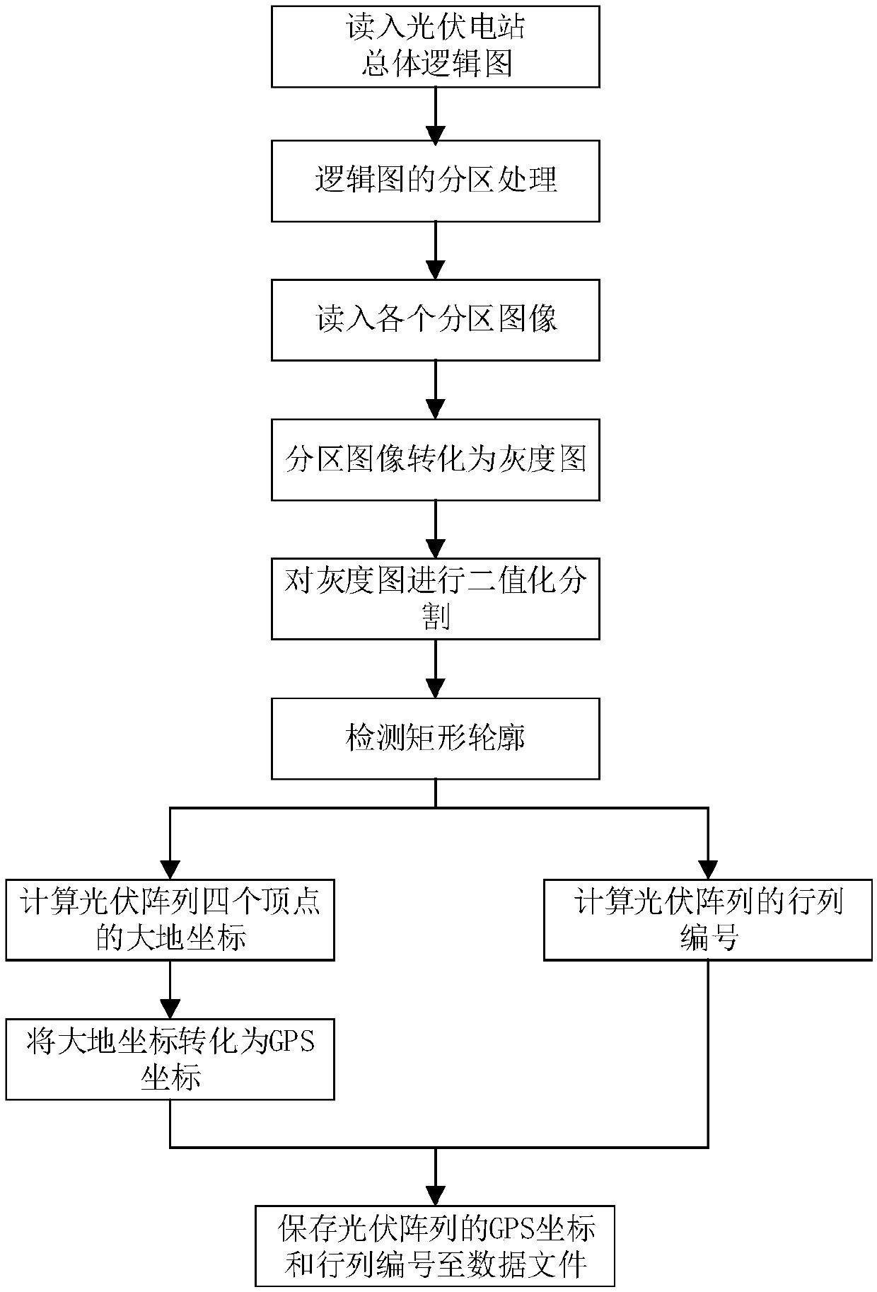
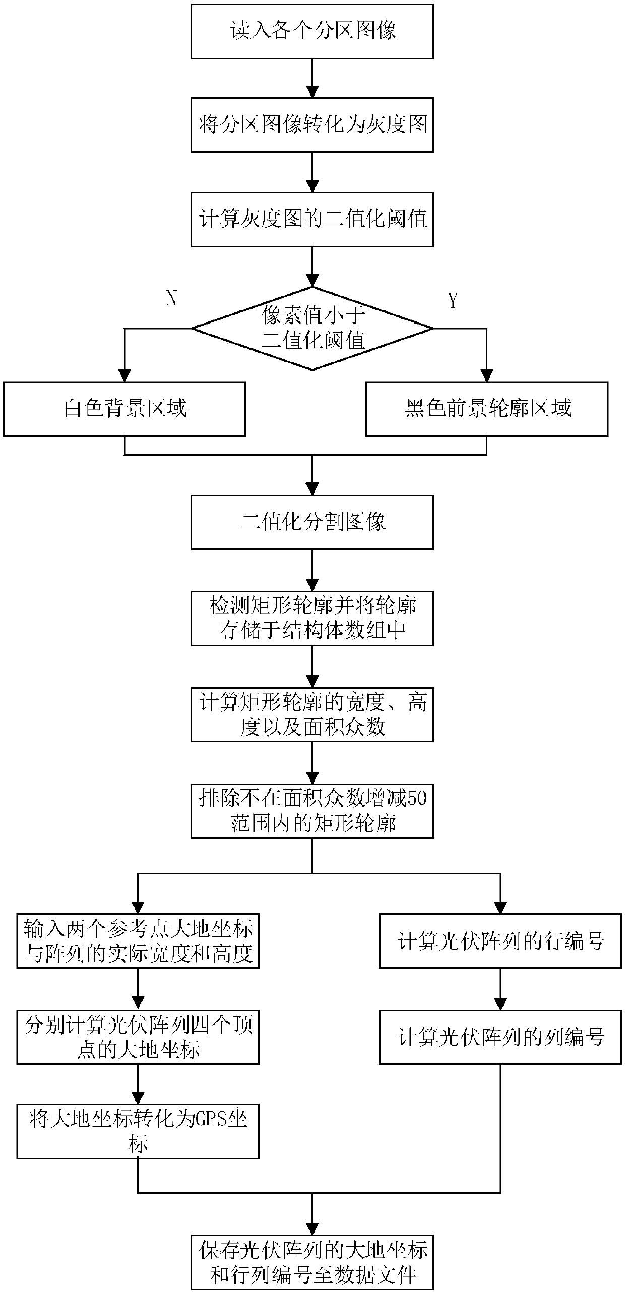
[0034] Such as figure 1 and figure 2 As shown, the array automatic detection and numbering method based on the logic diagram of the photovoltaic power station of the present invention is an image to be processed with the total logic diagram 1 of the photovoltaic power station, and its specific implementation plan is as follows:

[0035] 1) Firstly, manually partition according to the different line spacing between the arrays in the general logic diagram I, and obtain the partition image I i , where i=1,2,3,...,K, where K is the number of partition images, partition image I i The storage format is also not limited, and can be the same as the general logic diagram 1, such as the common JPEG format.

[0036] 2) For each partition image I i Process sequentially to obtain a binary image that separates the contours of the background and the foreground (that is, the ph...


PUM


Abstract

The invention discloses a photovoltaic power station logic diagram-based array automatic detection and numbering method. The method comprises the steps of firstly performing zoning on a photovoltaic power station main logic diagram to obtain a zoning image, removing color information of the zoning image to obtain a grayscale image, and performing binary threshold segmentation on the grayscale image to obtain a binary image with separated background and foreground (namely, an array profile); secondly, extracting a rectangular profile of the binary image, eliminating a false profile and noise interference by calculating modal information of the rectangular profile, and extracting an accurate array rectangle; and finally performing row and column numbering on each array, calculating geodetic coordinates of four vertexes of an array, converting the geodetic coordinates into GPS coordinates, and storing row and column numbers and GPS coordinate information in data files. According to the method, the position and number information of the array can be provided for applications such as automatic route planning of an unmanned aerial vehicle during shooting of a photovoltaic power station infrared image for performing cruising, hotspot detection and locating, and the like; and the technical support is provided for improving the automation level of photovoltaic power station fault detection.

Description

technical field [0001] The invention relates to an array automatic detection and numbering method based on a logic diagram of a photovoltaic power station, and belongs to the technical field of automatic analysis of array faults in a photovoltaic power station. Background technique [0002] In recent years, the photovoltaic power generation industry has entered a stage of rapid development worldwide, and the scale of photovoltaic power plants is also increasing. Each array of a large-scale photovoltaic power station usually has the characteristics of regular arrangement, large number, and wide distribution area in terms of geographical location, which greatly increases the workload and difficulty of fault detection. At present, the automation level of array fault (such as hot spot) detection is not high, and all array components are mainly detected by manual electrical measurement method, which has high labor cost and low efficiency. However, the method of detection by hand...

Claims


Application Information

Patent Timeline
IPC IPC(8): G06F17/50G06T7/11G06T7/194G06T7/13
CPCG06F30/00G06T7/11G06T7/13G06T7/194G06T2207/10004
Inventor 崔子冠荣金莉陈亮干宗良唐贵进刘峰
Owner NANJING UNIV OF POSTS & TELECOMM
Why Eureka
Eureka Blog
Learn More