
FPGA-based full-mode Cameralink digital image optical transceiver receiving terminal and transmitting terminal

A digital image and optical transceiver technology, applied in the field of long-distance transmission, can solve the problem that the sending end and the receiving end cannot be used universally, and achieve the effect of high bandwidth, high adaptability, and flexible use

Active Publication Date: 2017-12-01
CHANGCHUN INST OF OPTICS FINE MECHANICS & PHYSICS CHINESE ACAD OF SCI
View PDF9 Cites 28 Cited by
  • Summary
  • Abstract
  • Description
  • Claims
  • Application Information

AI Technical Summary

Problems solved by technology

[0005] The present invention aims to overcome the technical defects that the sending end and receiving end of the existing digital image optical transceivers cannot be used universally and rely on codec chips, and provide a FPGA-based full-mode Cameralink digital image optical transceiver sending end and Receiving end

Method used


Image

  • FPGA-based full-mode Cameralink digital image optical transceiver receiving terminal and transmitting terminal
  • FPGA-based full-mode Cameralink digital image optical transceiver receiving terminal and transmitting terminal
  • FPGA-based full-mode Cameralink digital image optical transceiver receiving terminal and transmitting terminal

Examples


Embodiment Construction

[0048] In order to make the object, technical solution and advantages of the present invention clearer, the present invention will be further described in detail below in conjunction with the accompanying drawings and specific embodiments. It should be understood that the specific embodiments described here are only used to explain the present invention, but not to limit the present invention.

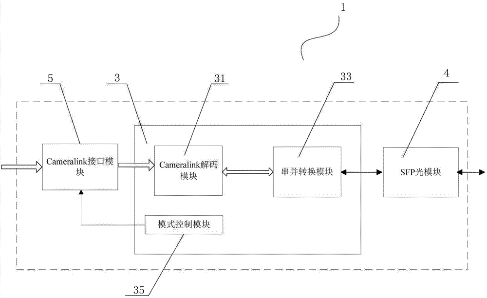
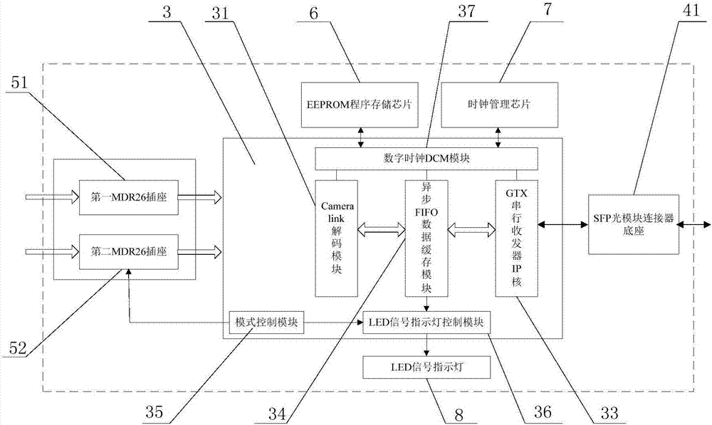
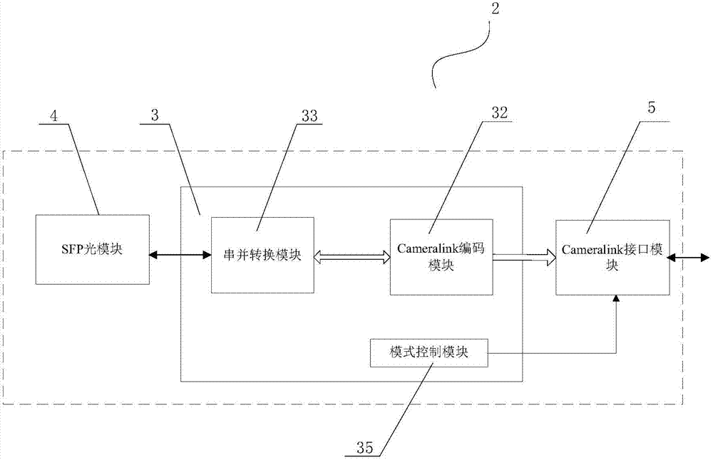
[0049]The digital image optical transceiver includes a digital image sending end 1 and a digital image receiving end 2, and the two communicate through an optical fiber connection; the sending end 1 converts the image data input into the Cameralink interface and the camera serial communication signal into an optical signal, and sends it to The receiving end 2, the receiving end 2 converts the optical signal into a corresponding image signal and a serial communication signal and outputs it from the Cameralink interface. The sending end 1 receives the camera control signal and the camera...


PUM


Abstract

The invention relates to the technical field of Cameralink high-speed digital image long distance transmission, and particularly discloses an FPGA-based full-mode Cameralink digital image optical transceiver transmitting terminal comprising an FPGA chip, a Cameralink interface module and an SFP optical module. The FPGA chip comprises a series-to-parallel signal conversion module, a Cameralink decoding module and a mode control module. The Cameralink interface module receives a Cameralink signal and transmits the Cameralink signal to the Cameralink decoding module. The Cameralink decoding module decodes serial data and transmits the decoded serial data to the series-to-parallel signal conversion module. The series-to-parallel signal conversion module performs series-to-parallel conversion on the received digital image signal so as to form the serial data stream. The SFP optical module receives the serial data stream and converts the serial data stream into an optical fiber signal. The mode control module controls the work mode of the transmitting terminal. Correspondingly, the invention also discloses an FPGA-based full-mode Cameralink digital image optical transceiver receiving terminal. FPGA chip software setting is utilized to replace the conventional coding and decoding chip so that the transmitting terminal and the receiving terminal of the optical transceiver are enabled to be identical in hardware structure, and the beneficial effect of increasing system integration can be achieved.

Description

technical field [0001] The invention relates to the technical field of long-distance transmission of Cameralink high-speed digital images, in particular to an FPGA-based full-mode Cameralink digital image optical transceiver. Background technique [0002] In the field of cameralink digital image transmission technology, in the traditional transmission mode, the transmission medium between devices is directly connected by cameralink data line, which makes it poor in anti-interference and short in transmission distance. (CameraLink is a serial communication protocol specifically for machine vision applications, using low-voltage differential signals for LVDS transmission; LVDS, Low Voltage Differential Signaling, is a low-voltage differential signal technology interface.) [0003] Because optical fiber transmission has the advantages of good confidentiality, strong anti-interference performance, high transmission rate and large capacity, there are more and more Cameralink imag...

Claims


Application Information

Patent Timeline
Patent Type & Authority Applications(China)
IPC IPC(8): H04N7/22
CPCH04N7/22
Inventor 张维达张甫恺崔明曹永刚吴志勇
Owner CHANGCHUN INST OF OPTICS FINE MECHANICS & PHYSICS CHINESE ACAD OF SCI
Learn More