Heat dissipation structure of a charging pile

A heat dissipation structure and charging pile technology, applied in the modification of power electronics, electrical equipment structural parts, electrical components, etc., can solve the problems that heat cannot be extracted in time, limit the application range of charging piles, and the volume of charging piles is huge. Achieve good heat dissipation effect, compact structure, and save floor space

Active Publication Date: 2020-07-28
SHENZHEN KEHUA HENGSHENG TECH
View PDF8 Cites 0 Cited by
  • Summary
  • Abstract
  • Description
  • Claims
  • Application Information

AI Technical Summary

Problems solved by technology

However, when such a heat dissipation structure is used for heat dissipation, due to the limitation of the power of the fan structure, the number of fans, or the structure of the air outlet, the heat cannot be extracted in time, and it is easy to accumulate on the air outlet side, thereby affecting the heat dissipation effect. Installing a fan requires a separate space in the charging pile integrated machine, which makes the charging pile often bulky and limits the scope of application of the charging pile. Therefore, the heat dissipation structure of the existing charging pile still needs to be further improved

Method used


Image

  • Heat dissipation structure of a charging pile
  • Heat dissipation structure of a charging pile
  • Heat dissipation structure of a charging pile

Examples


Embodiment Construction

[0031] In order to make the technical problems, technical solutions and beneficial effects to be solved by the present invention clearer and clearer, the present invention will be further described in detail below in conjunction with the accompanying drawings and embodiments. It should be understood that the specific embodiments described here are only used to explain the present invention, not to limit the present invention.

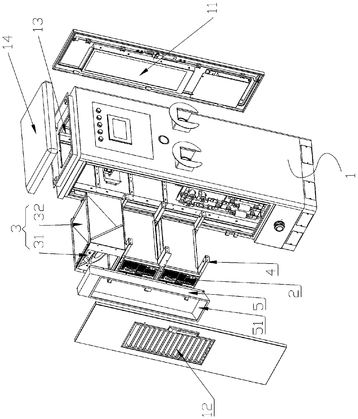
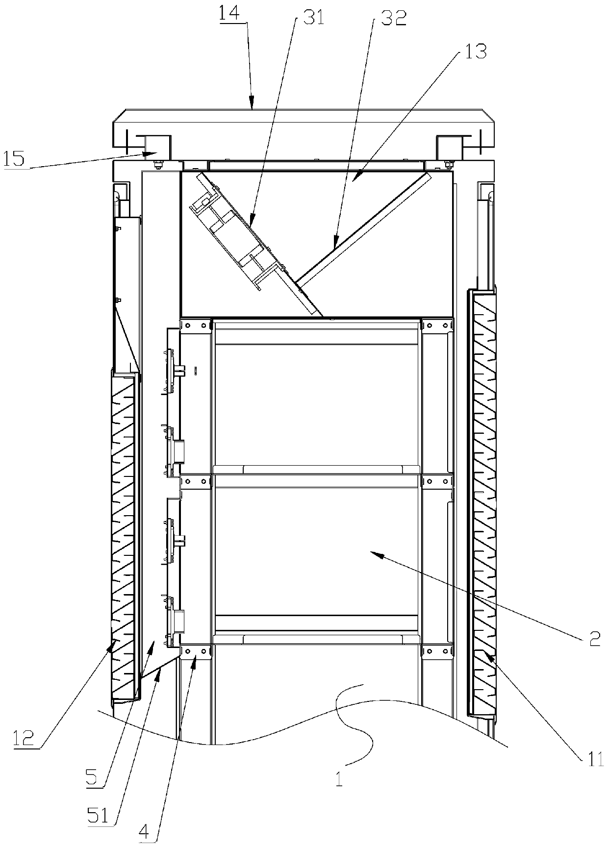
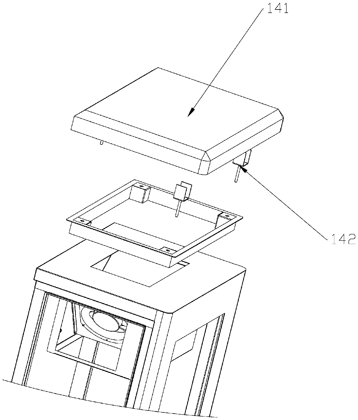
[0032] Such as figure 1 , figure 2 and image 3 shown. A heat dissipation structure of a charging pile, comprising a cabinet body 1, an electrical module 2, and a heat dissipation drive unit 3; and the side air outlet 12 are louver-type strip holes, and the louver-type strip holes are inclined from top to bottom to the outside of the cabinet body 1, effectively preventing rainwater from entering the cabinet body, and avoiding when placing electrical modules inside the cabinet body. In order to cause safety hazards or accidents to the machine. The ...


PUM


Abstract

The invention discloses a heat dissipation structure of a charging pile, which includes a cabinet body, an electrical module, and a heat dissipation drive unit; the lower part of the cabinet body is relatively provided with a lateral air inlet and a lateral air outlet, and the upper part of the cabinet body is provided with an opening; The electrical module is located between the lateral air inlet and the lateral air outlet, and a cooling fan is provided in the electrical module, and the cooling fan is used to guide the wind from the lateral air inlet of the cabinet to the lateral air outlet of the cabinet; The heat dissipation drive unit is installed inside the upper part of the cabinet; the air inlet of the heat dissipation drive unit forms an upper air intake channel with the electrical module and the lateral air outlet of the cabinet; the air outlet of the heat dissipation drive unit is connected to the An upper air outlet channel is formed between the openings on the upper part of the cabinet body. The charging pile of the invention has the advantages of compact structure, small occupied area, high heat dissipation efficiency and wide applicability.

Description

technical field [0001] The invention relates to the field of new energy charging pile equipment manufacturing, in particular to a heat dissipation structure of a charging pile. Background technique [0002] At present, the heat dissipation of some charging pile integrated machines is usually provided with a fan structure on one door panel, and an air inlet hole is provided on the other opposite door panel. When cooling, the heat in the integrated machine is drawn to the outside through the operation of the fan. At this time, the cold air passes through the air inlet hole, passes through the electrical module in the charging pile integrated machine, and is then pumped to the outside by the fan structure on the other side. However, when such a heat dissipation structure is used for heat dissipation, due to the limitation of the power of the fan structure, the number of fans, or the structure of the air outlet, the heat cannot be extracted in time, and it is easy to accumulate ...

Claims


Application Information

Patent Timeline
Patent Type & Authority Patents(China)
IPC IPC(8): H05K7/20H05K5/02
CPCH05K5/0213H05K5/0217H05K7/20145H05K7/20909H05K7/20945H05K5/03
Inventor 王斌梁舒展张黎鸿林志良
Owner SHENZHEN KEHUA HENGSHENG TECH
Why Eureka
Try Eureka